OSA Standards Committee eds. Ronald K. Kimmel and Robert E. Parks
We hope you appreciate this republication of ISO 10110 Optics and Optical Instruments—Preparation of Drawings for Optical Elements and Systems: A User’s Guide, first published in 1995. This open-access republication is intended to give you a feel for the ISO 10110 standard and an overview of its general scope and methodology. It is not intended for use as a standard as it is hopelessly out of date. Copyright 1995
When you have convinced yourself of the usefulness of ISO 10110, go to www.ISO.org or www.ANSI.org and order the standard. Yes, we know it is pricey, but it is a cost of doing business in the optics industry. Ultimately, using the standard will save you money. The advantage of using ISO 10110 is that the optics world is global and, if your drawings are done according to this standard, they will be more likely to be understood worldwide.
If you find there are parts of ISO 10110 that put you to a disadvantage, or you have something to add to the standard, please contact Patrick Augino at the Optics and Electro-Optics Standards Council (OEOSC) Exec_Director@oeosc.org and join OEOSC. OEOSC is the US ANSI member of the ISO optical standards writing committee, TC172. As a member of OEOSC you will have the opportunity to work on updates to the standard and will receive proposed updates for review and approval.
The other day I got a call from a PSM user asking about calibration. What he was really asking about was the setting of the zero, or origin, on the video screen.
CROSSHAIRS IN THE CENTER OF THE FIELD
This is the same sort of “calibration” people talk about when using autocollimators, which are the crosshairs in the center of the field. Here you can use a corner reflector or rotate the collimator in its mount to see if the target appears to move. If the target moves as the autocollimator is rotated about its axis, the crosshairs are not centered. (For more on autocollimators, see below.)
EQUIVALENT CALIBRATION
The equivalent calibration for the PSM is to focus on a specular surface to get a well-focused return spot, a Cat’s eye reflection, and click the Set Ref Pnt button to center the crosshairs on the return spot electronically. This operation is the equivalent of bore sighting a rifle scope. When the crosshair is centered on the Cat’s eye reflection the focus of the PSM objective is centered in the crosshair.
Thus, when a return reflection is also centered in the crosshair, the return reflection is coincident with the outgoing light focus. In this way you can be sure you are at the center of curvature of a concave mirror to better than 1 μm when the PSM is used with a 10x objective, the standard sold with the PSM. Obviously, a higher resolution is achieved with a higher power objective.
THE CALIBRATION FACTOR
If by calibration you mean when the PSM says the return spot is 54.2 μm from the crosshair, is it really 54.2 μm or is it 54.4 μm?
For most users, simply setting the Calibration Factor to 1.00 when using the standard 10x objective is good enough. For those who want to know the distance to the last μm the answer is to use a calibrated line width standard and measure it to see if the value you get with the PSM is the same as the standard. If it is not, the Calibration Factor can be tweaked to give a precise reading.
When using an objective other than the 10x Nikon objective supplied with the PSM you may want to change the Calibration Factor to get the correct reading in μms. For those not having a suitable line width standard, we have standards traceable to NIST for sale in our webstore.
THE PSM ALSO WORKS AS AN AUTOCOLLIMATOR
Recently we have sold several PSMs to a customer that wanted the PSM strictly as an autocollimator.
They wanted to build the PSM autocollimators into their hardware as permanent measurement devices and did not have space or stiffness to support a standard autocollimator that tends to be 500 mm or so long and weighs several kilograms.
As you may (or may not) know, the PSM works as an autocollimator by simply removing the objective and it has a resolution of better than 1 arc second.
For this particular customer, the PSM was a perfect solution since the PSM is about the size of your hand and weighs about half a kilogram. Another advantage for this customer was that their target was rather small, less than 10 mm in diameter. This fit nicely with the PSM collimated beam output diameter of 6 mm, much better than a standard autocollimator with a beam diameter of over 25 mm where most of the light falls off the target or is reflected as scattered light.
MACHINE VISION AUTOMATION SCHEME FOR LIMITED SPACE
I am publishing this article, because I got the call from someone who wanted a PSM as an autocollimator for just this reason, to incorporate in a machine vision, automation scheme with limited space.
This got me thinking that we have always stressed using the PSM for alignment and centering and have treated its use as an autocollimator as a very secondary use.
The call from the customer who wanted to use the PSM for an autocollimator, made me realize that there is a customer base who really needs a compact, electronic autocollimator. The PSM may be just what they are looking for.
In general, computer generated holograms (CGHs) and plane Fresnel mirrors (and lenses), made by the same techniques as CGHs, have optical “datums” or foci that are “rigidly attached” to the CGH or Fresnel plane substrate and move in six degrees of freedom with the substrate.
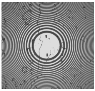
THIS CONCEPT IS MORE EASILY SEEN BY CONSIDERING A GRATING PATTERN FOR A FRESNEL SPHERICAL MIRROR AS SHOWN IN FIG. 1.
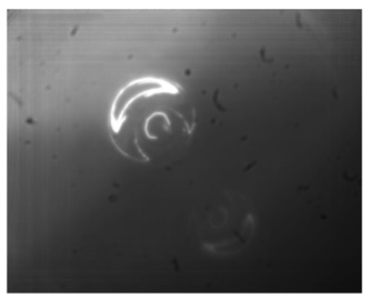
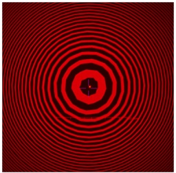
Fig. 1 Chrome on fused silica Fresnel zone pattern for a spherical mirror. The extraneous artifacts that look like contamination is contamination from incomplete cleaning of the pattern
This two-dimensional Fresnel zone pattern will reimage a point source placed at its center of curvature exactly the same as if it were a three dimensional solid spherical mirror and will re-image the point source in transmission as though it were a solid lens. It is obvious that if this pattern moves in three degrees of translation and two degrees of tilt the center of curvature will move with the substrate. For a Fresnel mirror of an off-axis ellipse or hyperbola with two foci not on a line perpendicular to the substrate, the foci will move in all six degrees of freedom with the substrate.
Thus the center of curvature or foci move with the substrate as though they were rigidly attached even though you cannot see or physically touch the foci. The foci are only visible by putting a point source of light at one focus and viewing the reflected point image at the other. The CGHs behave the same way. The aspheric wavefront they produce moves with the substrate. If you know where the substrate is in space (and the design of the pattern) you know by analysis where the foci are and vice versa.
THE PROBLEM IS HOW DO YOU RELATE THE FOCI TO THE SUBSTRATE SO THE FOCI OR ASPHERIC CGH PATTERN ARE PRECISELY LOCATED WHERE YOUR OPTICAL DESIGN SPECIFIES.
One solution is to print spherical Fresnel zone patterns at known locations relative to the main pattern during the same process as the main pattern is written. Then you know the centers of curvature of the Fresnel patterns relative to the main pattern with a precision on the order of tens of nanometers. Now the challenge is to turn these virtual centers of curvature into something physical that can be probed with a coordinate measuring machine, a laser tracker or to serve as seats for a kinematic mount.
We follow an idea first described by Laura Coyle1 where steel balls were centered on the spherical Fresnel mirror patterns but modify the concept to make it what we think is more practical to implement. What we will describe is not the only method. A commercial vendor of CGHs is using another method that is an offshoot of the Coyle method2.
Instead of mounting balls directly to the CGH substrate, a method we found awkward and tedious3, we attach spherically mounted retroreflector (SMR) nests to the substrate over the Fresnel patterns to give a more solid mounting method and to reduce the final height of the attachment except for when metrology is needed.
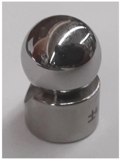
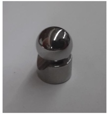
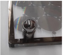
Fig. 2. A ½” Grade 5 steel ball seated in a ½” SMR nest manufactured so the center of the ball is ½” above the bottom of the nest
Because this variety of SMR nest is made so that it holds the center of the ball ½” above the bottom of the nest within 10 μm, we specify that the Fresnel pattern over which the ball/nest pair are mounted have a ½” radius of curvature. We also specify where the centers of the Fresnel patterns are located in the plane of the CGH to the main pattern. This means we know where the Fresnel pattern centers of curvature are relative to the main pattern to tens of nm in the plane of the substrate and ± 5 μm perpendicular to the substrate.
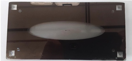
FIG. 3 SHOWS AN EXAMPLE OF THE FRESNEL OFF-AXIS CONIC TO WHICH WE WILL ATTACH THE BALL/NEST PAIRS.
Fig. 3. Off-axis plane Fresnel conic mirror
The square patterns in the corners of the CGH in Fig. 3 are the patterns the vendor would use to position balls. The circular patterns just inside the square patterns are the spherical mirror patterns we will use.
In order to attach the nest/ball pairs the CGH is held firmly on a vacuum chuck beneath a PSM focused on the pattern. The CGH is tapped gently to center the Fresnel pattern (Fig. 1) under the PSM. Then the PSM is raised ½” to pick up the center of curvature of the Fresnel pattern. By first centering the PSM on the pattern itself it is easy to pick up the center of curvature because it is guaranteed to be in the PSM field of view.
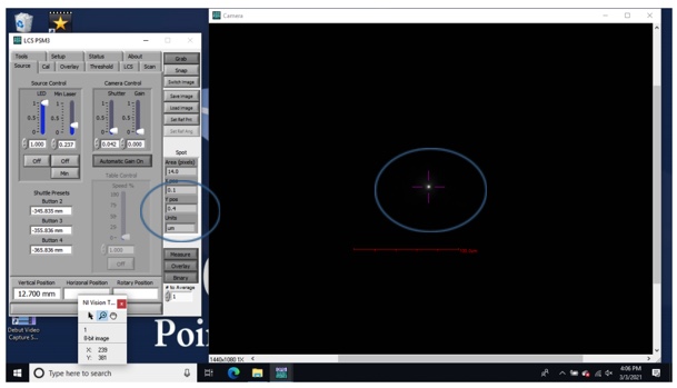
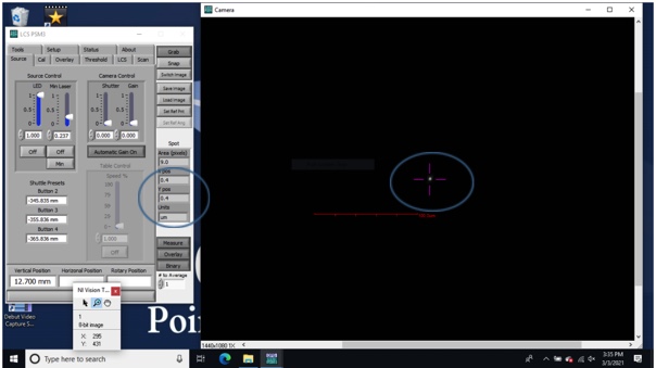
WITH THE CENTER OF CURVATURE IN THE FIELD OF VIEW, THE SET REF POS BUTTON IN THE PSM SOFTWARE IS CLICKED TO CENTER THE ELECTRONIC CROSSHAIR ON THE RETURN SPOT AS IN FIG. 4.
Fig. 4 Screenshot of the electronic crosshair centered on the return spot to 0.1 and 0.4 μm in x and y respectively
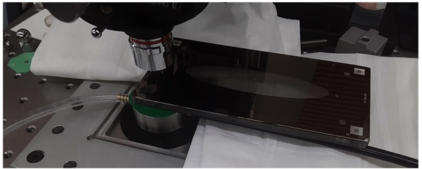
WITH THE CGH STILL FIRMLY HELD, SEE FIG. 5, A BALL/NEST PAIR ARE SLID ONTO THE CGH AND ROUGHLY CENTERED OVER THE FRESNEL PATTERN, FIG. 6.
Fig. 5 CGH held on a vacuum chuck under the PSM centered on the Fresnel pattern.
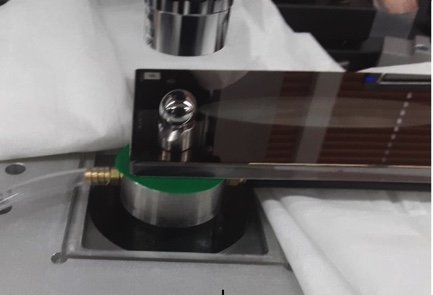
Fig. 6 Ball/nest pair sitting on the CGH over the Fresnel pattern.
BY GENTLY TAPPING THE BALL/NEST PAIR THE REFLECTED SPOT FROM THE BALL CENTER CAN BE CENTERED ON THE CROSSHAIR TO LESS THAN 1 ΜM. IT TAKES A MINUTE AT MOST TO POSITION THE BALL/NEST PAIR TO THIS PRECISION. THE SCREENSHOT IN FIG. 7 SHOWS THE RESULT OF THIS ALIGNMENT TO 0.4 AND 0.4 ΜM IN X AND Y RESPECTIVELY.
Fig. 7 Reflected spot from the ball center centered on the electronic hair.
With the ball/nest pair centered on the crosshair now carefully add drops of cement at the nest/CGH interface while checking the PSM software that you have not disturbed the alignment of the pair. Five minute epoxy is a good choice for cement because it gives you a small time window in case the pair moves. Also, the epoxy will not “set” in 5 minutes. More like 10 to 15 minutes before it is safe to move the CGH to the next Fresnel pattern. After an overnight cure you may want to add a little addition epoxy to fully secure the nests. Fig. 8 gives an idea of what the drops of cement might look like.
Also, the cement tends to pull out into a thin hair when you pull your applicator away from the drop of cement. Make sure the hair does not fall on the main CGH pattern. It may be well to protect the pattern before cementing.
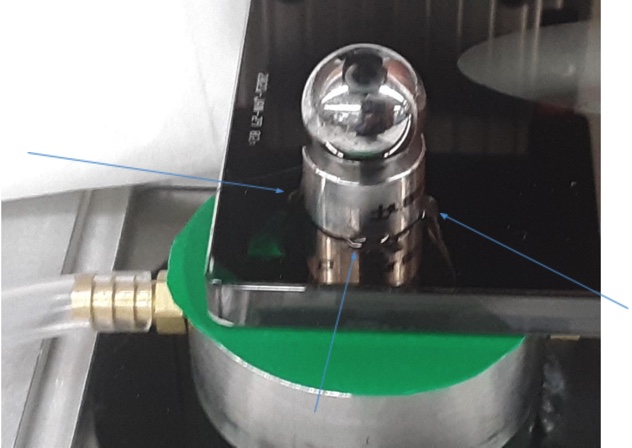
Fig. 8 Drops of cement at the base of the nest to secure the nest to the CGH.
In all it will take about an hour to secure all four ball/nest pairs to a CGH. It would be wise to wait a day before removing the balls from the nests as the balls are held in with a magnet and it requires some force to remove the balls.
When finished you will have four balls attached to the substrate within < 1 μm each of their ideal location in the plane of the CGH and within ± 5 μm perpendicular to the substrate. If more precision is required perpendicular to the substrate the nests can be lapped on fine silicon carbide lapping paper until the required ball/nest height match is met. The PSM can be used to determine this height by looking in at the side of the ball where there is the higher lateral sensitivity.
1 L. E. Coyle, M. Dubin, and J. H. Burge, “Locating computer generated holograms in 3D using precision aligned SMRs,” in Classical Optics 2014, OSA Technical Digest (online) (Optical Society of America, 2014), paper OTh1B.2. https://www.osapublishing.org/abstract.cfm?URI=OFT-2014-OTh1B.2
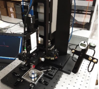
Recently, a client asked how well can you focus if you really had to do better? I did not know but it was easy to do an experiment with our centering station that has a motorized stage and the ability to log data as the stage moves.
It is easily demonstrated that the PSM lateral sensitivity to centroiding on a return reflection from a center of curvature is better than 1 μm with a 10x objective. In the usual case the sensitivity is better than 0.2 μm. However, the sensitivity axially, or in the direction of focus is less sensitive, typically ± 2-3 μm judging by the size and shape of the image on the video screen.
WAS I SURPRISED BY THE RESULTS!
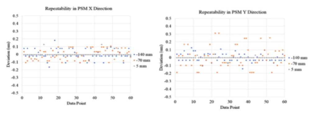
Using our centering station I got repeatability of better than 0.1 μm using the center of a 1/8” steel ball as my mirror and a 10x objective with a NA of 0.25 on the PSM. Classically, the depth of focus is λ/2*NA or about 0.635/.5 = 1.27 μm in this case.
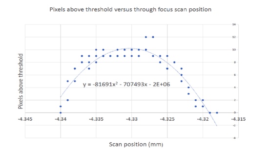
To do the experiment to find focus you have to adjust the shutter speed on the PSM so there are about 10-15 pixels above threshold at what appears from the video screen to be best focus. The area designation on the PSM control panel is a count of the number of pixels above threshold so the illumination is easy to set to get the right number of pixels. Then you scan through where you expect best focus while logging the number of pixels above threshold as you scan. These data are saved to a file that is then copied to Excel. When the data of number of pixels versus scan position are plotted as in the graph below you can fit a second order polynomial as shown in the equation on the chart.
Remembering that we can find the maximum of the curve by taking the derivative and setting it to zero, we get -2*81691*x -707493 = 0, or x = 4.3303 mm. When this scan was repeated another 4 times I got 4.3303, 4.3302, 4.3303 and 4.3301 mm as the scan position at maximum pixels above threshold. This represents repeatability of less than 0.1 μm even though the data are rather noisy due to the small number of pixels used in the data.
This experiment points out the advantage of using a digital camera on the PSM. Without the ability to digitize the intensity at each pixel it would be impossible for this process to work.
The exact set of parameters used in this experiment may not be optimized, but this data shows the remarkable sort of focus repeatability that can be achieved with the PSM. It may be possible to do even better.
I needed to measure the height of a free space fiber termination above an optical bench the other day and in the process remembered a question I had been asked in passing. Since I had the pieces of such an experiment in front of me, all I had to do was save a couple of images.
In this case I was looking at the end of a single mode fiber patch cord to set it a particular distance above an optical breadboard.
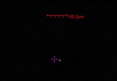
With the laser turned on at a minimum intensity the light from the fiber looks like this zoomed in image of about 400 x 300 pixels of the whole 1.6 M pixel frame.
The laser spot (white dot) was purposely decentered from the magenta cross that is the origin of the PSM coordinate system so the shape of the spot could be clearly seen to get best focus. The centroid of the spot was measured to 0.2 μm in x and y using a 4x objective on the PSM.
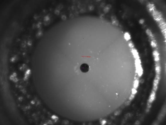
Without touching anything other than turning off the laser source and shining a light past the objective to illuminate the front of the fiber I got this image of the 2.5 mm diameter fiber ferrule with the 125 μm core embedded in its center.
If you squint you can still see the magenta cross and the red scale bar to give a feel for the relative scale of the 2 pictures. The faint darker cross at 45 degrees gives a hint as to how the ceramic ferrule extrusion was made.
GOOD NEWS FOR THE NEW YEAR, THE STANDARD PSM WORKS IN THE NEAR IR
Many times potential customers have asked “How far does the PSM work into the infrared?” I told them the standard PSM works as far out as 1050 nm with the CMOS camera that comes with every new PSM because I have used the PSM there with a fiber coupled external source. But some customers want to go farther into the IR.
PART 1: EXPERIMENTS WITH IR CAMERAS
USING THE PSM TO SEE THROUGH SILICON
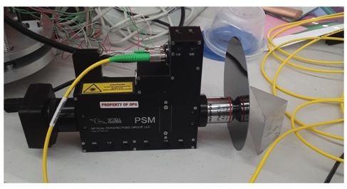
Recently we purchased a camera that is sensitive out to 1600 nm and a laser source at 1550 nm to see if we could use the PSM to see through silicon. It works! We did the most simple minded experiment of putting a silicon wafer between the PSM objective and a front surface plane mirror as in the photo.
This shows that with an external laser source and a fairly inexpensive NIR camera the standard PSM is useful for aligning lenses containing silicon optics. It had been my worry that one of the lenses in the PSM, or a beamsplitter coating, would prevent the PSM from working at this wavelength. The standard PSM works just fine with the addition of the NIR C mount camera.
Some people, however, want to look through germanium that becomes transparent at 1900 nm or so. The inexpensive NIR camera does not work for this. But the question for me remained, is there something in the PSM or objective that would block light in the region that germanium transmits. Mark Christenson, a representative of Envisionate offered to get a Xenics Xera 2.35 camera to try out with the PSM. With a 6 mm uncoated germanium window sitting in front of the objective we could see the filament of an incandescent heat lamp, see below.
IMAGE OF A HEAT LAMP FILAMENT VIEWED THROUGH A 6 MM GERMANIUM WINDOW WITH THE PSM
This is hardly a sophisticated experiment but it proves there is nothing in the PSM that prevents use of a camera sensitive out to 2350 nm. This is not an inexpensive camera, but if you already own a PSM, you can simply screw this camera on to the PSM C mount and bring in a fiber coupled source at around 2 um and be ready to align lenses with germanium optics. In this case, Optical Perspectives is not going to purchase the camera for you, but if you have or can borrow a camera, we will provide a PSM so you can demo the idea in your facility.
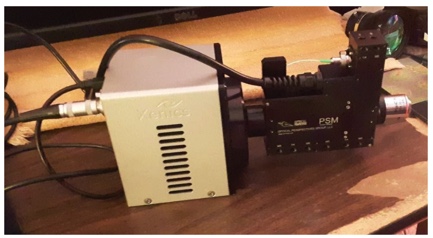
XENICS XEVA 2.35 CAMERA C MOUNTED TO THE PSM
The picture of the PSM mounted on the camera looks like the tail wagging the dog, but if that is what it takes, this is a solution to looking through germanium optics.
PART 2: PRECISION LOCATION OF CGHS
A METHOD OF PRECISELY LOCATING A COMPUTER GENERATED HOLOGRAM (CGH)
When using computer generated holograms (CGHS) to test aspheres and freeform optics it is essential that the CGH be precisely located relative to the interferometer transmission sphere and the optic under test. This location is often done with 3 balls mounted to the CGH to form a kinematically repeatable method of mounting the CGH. One of the limits to the precision is how well the balls align with the CGH pattern. We have a way of aligning the balls within a micrometer of their optimum location using the PSM provided there is a little planning in the design of the CGH.
In a prior paper* we talked about writing Fresnel zones on CGHs to simulate concave spheres for alignment purposes. If these Fresnel zones are written at the time the CHG null pattern for the asphere is written the zones will be within 10’s of nm of the desired location. We showed in the paper how a PSM is used to position a ball to a μm of the center of the Fresnel zone. As described in the paper the method of attaching the balls is it is awkward to implement.
A much better method is to use readily available Spherically Mounted Retroreflector (SMR) nests (used with laser trackers) to hold the balls. These nests have a magnet, a plane back and a precise cone to hold a precision ½” diameter ball. This makes a stable mount for the ball, it is easy to slide the nest/ball pair into place on the CGH and provides for good bonding to the CGH. The pictures below show the idea.
THIS PICTURE SHOWS JUST THE NEST AND A GRADE 5 CHROME STEEL BALL
THIS PICTURE ABOVE SHOWS HOW THE BALL AND NEST ARE POSITIONED OVER THE SMALL FRESNEL ZONE PATTERN THAT ACTS LIKE A CONCAVE MIRROR WITH A RADIUS OF CURVATURE JUST EQUAL TO THE HEIGHT OF THE CENTER OF THE BALL SITTING IN THE NEST
To position the nest/ball pair, the PSM picks up the center of curvature of the Fresnel zone and is adjusted so the reflected spot is well centered on the PSM crosshair. Then the nest/ball pair are slid into place so the ball center is centered on the crosshair. Now the ball center is precisely centered over the Fresnel zone pattern within 1 μm and the nest is cemented in place.
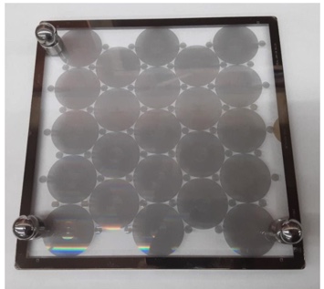
THREE NEST/BALL PAIRS PRECISELY POSITIONED ON A 6” PHOTOMASK SUBSTRATE AND CGH PATTERN
The finished CGH looks like this image with three nest/ball pairs ready to be set in a kinematic mount.
This method has several distinct advantages over some others.
First, the ability to position each of the balls within a μm of the precise location using the CHG pattern and the PSM.
Second, the SMR nest makes a stable platform on which to hold the ball while positioning it prior to cementing as opposed to the method shown in the paper.
Once the nests are bonded the balls are removable so there is a minimum of height above the CGH surface and the nests are held securely in place. An added advantage is that the position of the CGH can be determined either using a CMM and touch probing the balls, or the ball can be replaced with ½” SMRs and located with a laser tracker.
MICROPHOTOGRAPH OF THE CENTER OF THE FRESNEL ZONE PATTERN USED FOR POSITIONING THE NEST/BALL PAIRS
* Parks, R. E., “Optical Alignment using a CGH and an autostigmatic microscope”, Proc SPIE, 10377, 103770B, (2017), available in the Downloads>Bibliography accessible from the button below.