In general, computer generated holograms (CGHs) and plane Fresnel mirrors (and lenses), made by the same techniques as CGHs, have optical “datums” or foci that are “rigidly attached” to the CGH or Fresnel plane substrate and move in six degrees of freedom with the substrate.
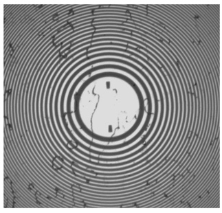
THIS CONCEPT IS MORE EASILY SEEN BY CONSIDERING A GRATING PATTERN FOR A FRESNEL SPHERICAL MIRROR AS SHOWN IN FIG. 1.
Fig. 1 Chrome on fused silica Fresnel zone pattern for a spherical mirror. The extraneous artifacts that look like contamination is contamination from incomplete cleaning of the pattern
This two-dimensional Fresnel zone pattern will reimage a point source placed at its center of curvature exactly the same as if it were a three dimensional solid spherical mirror and will re-image the point source in transmission as though it were a solid lens. It is obvious that if this pattern moves in three degrees of translation and two degrees of tilt the center of curvature will move with the substrate. For a Fresnel mirror of an off-axis ellipse or hyperbola with two foci not on a line perpendicular to the substrate, the foci will move in all six degrees of freedom with the substrate.
Thus the center of curvature or foci move with the substrate as though they were rigidly attached even though you cannot see or physically touch the foci. The foci are only visible by putting a point source of light at one focus and viewing the reflected point image at the other. The CGHs behave the same way. The aspheric wavefront they produce moves with the substrate. If you know where the substrate is in space (and the design of the pattern) you know by analysis where the foci are and vice versa.
THE PROBLEM IS HOW DO YOU RELATE THE FOCI TO THE SUBSTRATE SO THE FOCI OR ASPHERIC CGH PATTERN ARE PRECISELY LOCATED WHERE YOUR OPTICAL DESIGN SPECIFIES.
One solution is to print spherical Fresnel zone patterns at known locations relative to the main pattern during the same process as the main pattern is written. Then you know the centers of curvature of the Fresnel patterns relative to the main pattern with a precision on the order of tens of nanometers. Now the challenge is to turn these virtual centers of curvature into something physical that can be probed with a coordinate measuring machine, a laser tracker or to serve as seats for a kinematic mount.
We follow an idea first described by Laura Coyle1 where steel balls were centered on the spherical Fresnel mirror patterns but modify the concept to make it what we think is more practical to implement. What we will describe is not the only method. A commercial vendor of CGHs is using another method that is an offshoot of the Coyle method2.
Instead of mounting balls directly to the CGH substrate, a method we found awkward and tedious3, we attach spherically mounted retroreflector (SMR) nests to the substrate over the Fresnel patterns to give a more solid mounting method and to reduce the final height of the attachment except for when metrology is needed.
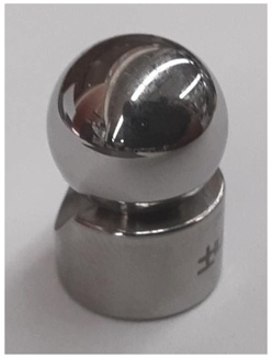
Fig. 2. A ½” Grade 5 steel ball seated in a ½” SMR nest manufactured so the center of the ball is ½” above the bottom of the nest
Because this variety of SMR nest is made so that it holds the center of the ball ½” above the bottom of the nest within 10 μm, we specify that the Fresnel pattern over which the ball/nest pair are mounted have a ½” radius of curvature. We also specify where the centers of the Fresnel patterns are located in the plane of the CGH to the main pattern. This means we know where the Fresnel pattern centers of curvature are relative to the main pattern to tens of nm in the plane of the substrate and ± 5 μm perpendicular to the substrate.
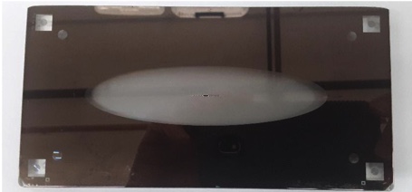
FIG. 3 SHOWS AN EXAMPLE OF THE FRESNEL OFF-AXIS CONIC TO WHICH WE WILL ATTACH THE BALL/NEST PAIRS.
Fig. 3. Off-axis plane Fresnel conic mirror
The square patterns in the corners of the CGH in Fig. 3 are the patterns the vendor would use to position balls. The circular patterns just inside the square patterns are the spherical mirror patterns we will use.
In order to attach the nest/ball pairs the CGH is held firmly on a vacuum chuck beneath a PSM focused on the pattern. The CGH is tapped gently to center the Fresnel pattern (Fig. 1) under the PSM. Then the PSM is raised ½” to pick up the center of curvature of the Fresnel pattern. By first centering the PSM on the pattern itself it is easy to pick up the center of curvature because it is guaranteed to be in the PSM field of view.
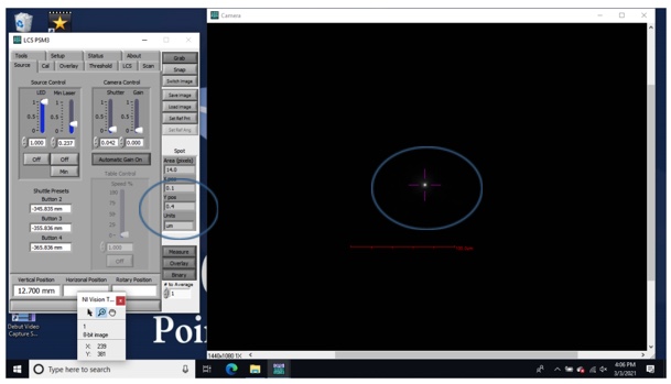
WITH THE CENTER OF CURVATURE IN THE FIELD OF VIEW, THE SET REF POS BUTTON IN THE PSM SOFTWARE IS CLICKED TO CENTER THE ELECTRONIC CROSSHAIR ON THE RETURN SPOT AS IN FIG. 4.
Fig. 4 Screenshot of the electronic crosshair centered on the return spot to 0.1 and 0.4 μm in x and y respectively
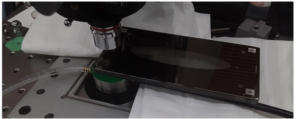
WITH THE CGH STILL FIRMLY HELD, SEE FIG. 5, A BALL/NEST PAIR ARE SLID ONTO THE CGH AND ROUGHLY CENTERED OVER THE FRESNEL PATTERN, FIG. 6.
Fig. 5 CGH held on a vacuum chuck under the PSM centered on the Fresnel pattern.
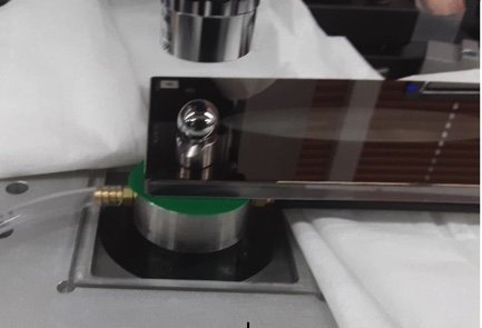
Fig. 6 Ball/nest pair sitting on the CGH over the Fresnel pattern.

BY GENTLY TAPPING THE BALL/NEST PAIR THE REFLECTED SPOT FROM THE BALL CENTER CAN BE CENTERED ON THE CROSSHAIR TO LESS THAN 1 ΜM. IT TAKES A MINUTE AT MOST TO POSITION THE BALL/NEST PAIR TO THIS PRECISION. THE SCREENSHOT IN FIG. 7 SHOWS THE RESULT OF THIS ALIGNMENT TO 0.4 AND 0.4 ΜM IN X AND Y RESPECTIVELY.
Fig. 7 Reflected spot from the ball center centered on the electronic hair.
With the ball/nest pair centered on the crosshair now carefully add drops of cement at the nest/CGH interface while checking the PSM software that you have not disturbed the alignment of the pair. Five minute epoxy is a good choice for cement because it gives you a small time window in case the pair moves. Also, the epoxy will not “set” in 5 minutes. More like 10 to 15 minutes before it is safe to move the CGH to the next Fresnel pattern. After an overnight cure you may want to add a little addition epoxy to fully secure the nests. Fig. 8 gives an idea of what the drops of cement might look like.
Also, the cement tends to pull out into a thin hair when you pull your applicator away from the drop of cement. Make sure the hair does not fall on the main CGH pattern. It may be well to protect the pattern before cementing.
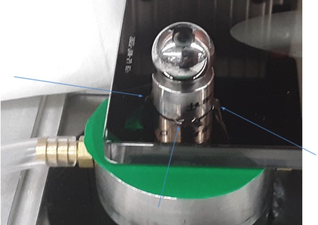
Fig. 8 Drops of cement at the base of the nest to secure the nest to the CGH.
In all it will take about an hour to secure all four ball/nest pairs to a CGH. It would be wise to wait a day before removing the balls from the nests as the balls are held in with a magnet and it requires some force to remove the balls.
When finished you will have four balls attached to the substrate within < 1 μm each of their ideal location in the plane of the CGH and within ± 5 μm perpendicular to the substrate. If more precision is required perpendicular to the substrate the nests can be lapped on fine silicon carbide lapping paper until the required ball/nest height match is met. The PSM can be used to determine this height by looking in at the side of the ball where there is the higher lateral sensitivity.
1 L. E. Coyle, M. Dubin, and J. H. Burge, “Locating computer generated holograms in 3D using precision aligned SMRs,” in Classical Optics 2014, OSA Technical Digest (online) (Optical Society of America, 2014), paper OTh1B.2.
https://www.osapublishing.org/abstract.cfm?URI=OFT-2014-OTh1B.2
2 Arizona Optical Metrology LLC, https://www.cghnulls.com
3 Parks, R. E., “Optical alignment using a CGH and an autostigmatic microscope “, Proc. SPIE, 10377, 103770B (2017)
4 Hubbs Machine & Mfg. Inc., https://hubbsmachine.com/