To center a lens, you make its optical axis, the line through the centers of curvature of its two surfaces, coincide with a reference axis. That reference can be the axis of a lens cell, a rotary table or a beam on an optical table. There are four practical ways to do it: measure edge thickness difference, rotate the lens and watch a reflected spot, view both centers of curvature with an autostigmatic microscope, or align the lens to a transmitted reference beam. The best choice depends on the lens size, how the cell constrains it, and the tilt and decenter you can tolerate.
This guide explains what each lens alignment method measures, where it works well and where it runs out of precision, then ends with a table to help you choose.
What does centering a lens actually mean?
A single spherical surface has no axis of its own. A lens element does, because it has two surfaces: its optical axis is the line that joins their two centers of curvature. That definition is independent of the lens edge and the seat. A poorly made lens can have an edge that is not concentric with its optical axis and a seat that is not perpendicular to it, yet the optical axis is still well defined.
That is why “centered” always means centered to something. When a lens is out of alignment, its optical axis is off the reference axis in two ways:
- Decenter: the axis is shifted sideways. A decentered lens bends the chief ray away from the axis, so the elements that follow behave as if they were tilted.
- Tilt: the axis is at an angle. A tilted lens displaces the chief ray, so the elements that follow behave as if they were decentered.
Correcting one without the other rarely finishes the job. Full alignment needs both tilt and decenter adjusted, and in a cell that fixes one degree of freedom, you have to decide which error to minimize.
Method 1: Edge thickness difference
Edge thickness difference (ETD) is the mechanical method, in use long before optical test instruments were common. The lens sits in a fixture: three small balls support one surface and fix its center of curvature, and two larger balls touch the edge. A dial indicator rests near the edge of the upper surface. The operator rotates the lens to find the maximum and minimum readings 180 degrees apart. The difference is the ETD, and dividing it by the lens diameter gives the wedge angle.
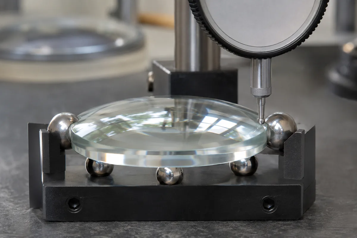
Cup edging machines use the same principle. The lens is squeezed between two coaxial cups, slides until the edge thickness is equal, and is then edged so its mechanical and optical axes coincide.
Where it fits: checking or correcting wedge before and after edging, and large optics. Bob Parks notes that ETD is still applied to elements nearly a meter in diameter for lithography lenses, while it is rarely used for small lens assemblies. Limitations: it is a contact measurement, its precision depends on the fixture and indicator, and it centers the lens to its own edge, not to the cell or the rest of the system. For the full fixture geometry and a worked example, see the chapter on centering using edge thickness difference.
Method 2: Rotate the lens and watch the reflected spot
The simplest optical method sends light to a surface and watches the reflection while the lens turns. Put a concave surface on a rotary table and focus a point of light near its center of curvature. If the center of curvature is not on the table’s axis of rotation, the reflected spot sweeps out a circle on the detector as the table turns. The larger the circle, the larger the decenter, so you adjust until the spot stops moving.
The method is sensitive because errors are doubled twice. Reflection doubles the displacement of the spot, and a 180 degree rotation moves the decenter to the opposite side. The point source also does not need to sit exactly on the table axis. It only needs to be close enough for the light to return to the objective. If the spot moves in step with the table at all, the surface is not centered.
Prototype optical shops often use a low-tech version: the lens is mounted on a single true-running cup with wax or vacuum, and the operator taps the edge until the reflected spot stops moving. Read more about centering on a rotary table with the PSM.
Where it fits: single surfaces, prototype work and quick checks. Limitations: you watch one center of curvature at a time. Centering one surface usually disturbs the other, so it becomes slow and iterative for a complete element.
Method 3: View both centers of curvature with an autostigmatic microscope
Because the optical axis runs through both centers of curvature, the most direct method is to watch both at once. In this setup the lens barrel sits on a precision air-bearing rotary table, and each element is centered on the table axis as it is placed in the barrel. An autostigmatic microscope, such as the Point Source Microscope (PSM), focuses its point source at a center of curvature, and the light returns as a focused spot on its camera.
Everything is viewed from above, through the upper surface. The rear surface’s center of curvature is seen after refraction through the front surface, so the lower side of a lens in a barrel never has to be accessed. A beamsplitter with a relay lens can send the two returns to two PSMs, so both centers are visible without moving an instrument. You then adjust tilt and decenter until neither spot moves as the table turns. A practical order is to center the front surface first, then the rear.
The sensitivity is high. In the published example, a 1 µm decenter of the front surface produces 4 µm of spot motion after a 180 degree rotation, before the objective’s magnification is applied, and the paper concludes that tilt and decenter can be corrected during assembly to the sub-micron and sub-second level. For the optical layout and the conjugate calculations, see the paper on lens centering with the Point Source Microscope.
Where it fits: multi-element assemblies in a barrel, where each element must line up with the cell axis and with the others. Limitations: it relies on the precision of the rotary table, and the setup needs relay optics chosen to reach each center of curvature.
Method 4: Align to a transmitted reference beam
The fourth method removes the rotary table. Instead, a beam defines the reference axis and the lens is moved in x and y until it sits on it.
An Axicon grating placed between a point source and a detector turns the spherical wave into a Bessel beam: a bright, narrow central core surrounded by rings. The core propagates along the line from the point source through the center of the grating pattern, so once the grating is centered, the Bessel beam becomes the system axis. An autostigmatic microscope then looks at a center of curvature of the lens and sees two things at once: the Bessel core and the reflection from the surface. When both are centered on the reticle, the element is aligned in tilt and decenter to the established axis, on the order of 1 µm and 1 arc second. For the step-by-step setup, read establishing a reference axis with an Axicon grating.
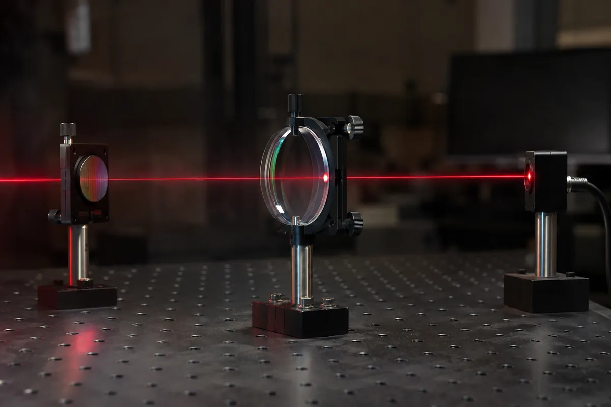
The method gives immediate x-y feedback without moving any part of the measurement setup, and it also works for whole lens assemblies, because an assembly has principal planes just like a single element. When a cell fixes the tilt, you can still use the remaining adjustment to keep the principal planes on the reference axis. One practical note: the detector must be pixelated so it can centroid on the central peak. Quad cells and continuous position-sensitive detectors are unsuitable, because the rings around the core have nearly uniform intensity.
Optical Perspectives Group builds this approach into the Axicon Grating Centering Station, designed for cementing doublets and assembling optical systems up to 250 mm in diameter. A Bessel beam is projected upward as the reference axis and a downward-looking PSM serves as the detector. It centers lenses in tilt to 1 arc second and decenter to 1 µm with a 10x objective, with no rotary table.
Where it fits: cemented doublets, tabletop systems and assemblies where a rotary table is impractical. Limitations: you first need a well-aligned reference axis, and the detector must be able to centroid a Bessel beam core.
Which lens alignment method fits your job?
Start with your tolerance. If you have not yet worked out how much tilt and decenter each element can take, use the guide to centering and tilt tolerances for your optical system first. Then match the method to the part and the setup.
| Method | What it senses | Typical use | Main limitation |
|---|---|---|---|
| Edge thickness difference | Wedge, by contact at the edge | Edging, large optics | Centers the lens to its own edge; contact measurement |
| Rotating reflected spot | One center of curvature at a time | Prototypes, single surfaces | Slow and iterative for both surfaces |
| Both centers with an autostigmatic microscope | Both centers of curvature, from above | Multi-element barrels on a rotary table | Needs a precise rotary table and relay optics |
| Transmitted reference beam (Bessel beam) | Beam core plus a center of curvature | Cemented doublets, tabletop systems, assemblies | Needs a reference axis and a pixelated detector |
Some quick rules of thumb follow from the sections above:
- If you are edging or inspecting a single element, ETD or a rotating reflected spot is often enough.
- If you are building a lens barrel, watch both centers of curvature so that fixing one surface does not undo the other.
- If you are cementing a doublet or aligning on an optical table, a transmitted reference beam gives direct x-y feedback without a rotary table.
- If the cell constrains tilt or decenter, decide which error matters more and use the remaining adjustment to minimize it.
Frequently asked questions
What is the optical axis of a lens?
It is the line that joins the centers of curvature of the lens’s two surfaces. It does not depend on the lens edge or seat, which is why a lens can be centered optically even when its edge is not concentric.
What is the difference between decenter and tilt?
Decenter is a sideways shift of the optical axis relative to the reference axis; tilt is an angle between them. Both must be corrected for complete alignment, and an error in one makes the following elements behave as if they had the other.
Can I center a lens with an autocollimator or an alignment telescope?
An autocollimator measures only two angles, so on its own it tells you about tilt, not decenter. An alignment telescope can focus at different distances and define a line in space, four degrees of freedom. Both are compared in the chapter on classical optical alignment instruments. For centering a lens element, viewing its centers of curvature directly is usually more convenient.
Do I need a rotary table to center a lens?
Not always. Methods 1 to 3 rely on rotation, but aligning to a transmitted Bessel beam reference uses x-y motion instead, which is how the Axicon Grating Centering Station works.