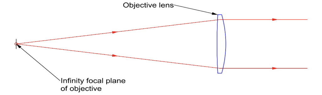
Fig. 1 A simple collimator with a point source of illumination. An illuminated target in the same plane could serve as the source.
Collimators are used as a light source for testing camera lenses on a nodal slide optical bench. The collimator simulates a point source, or in astronomical terms, a star, at infinity. For lens testing, the focal length of the collimator is typically 5 times or more the focal length of the lens under test so that the star appears “perfect” to the lens under test. Collimators are also used in MTF measuring instruments to project targets with a structured pattern into the lens under test to measure the lens quality.
An autocollimator (AC) is a collimator with a beamsplitter and an eyepiece so you can see where the reflected “star” falls in the eyepiece of the instrument, as in Fig. 2. A common method of packaging an AC is with a precision ground barrel designed to mate with a mount so that the axis of the barrel can be adjusted in 4 degrees of freedom (DOF). The reticle crosshair in the AC is centered on the axis of the barrel. When the AC barrel axis is normal to a plane mirror in front of the AC, the reflected image from the mirror will be centered on the crosshair and will not move when the AC is rotated about its axis.
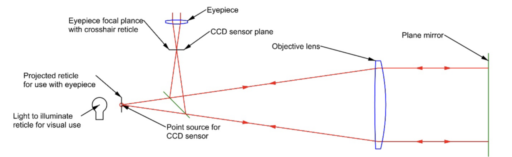
Fig. 2 Simple autocollimator shown for visual use, or for a point source and digital camera.
For autocollimators that do not have a mechanical reference axis such as a precision barrel, a cube corner reflector is used to center the reference crosshair on the axis of the instrument. The cube corner reflects light back upon itself so an image of the source as seen in the eyepiece is centered on the source. The crosshair in the eyepiece is set to zero on the image of the source.
Notice that an AC is only sensitive to two DOF, the two angles the plane mirror is tipped from being normal to the axis of the AC. Typical barrel type ACs have a full field of view of about +/- 1° but the reticle is labelled to give the angle between the plane mirror and the axis of the AC, or +/- 30 are minutes.
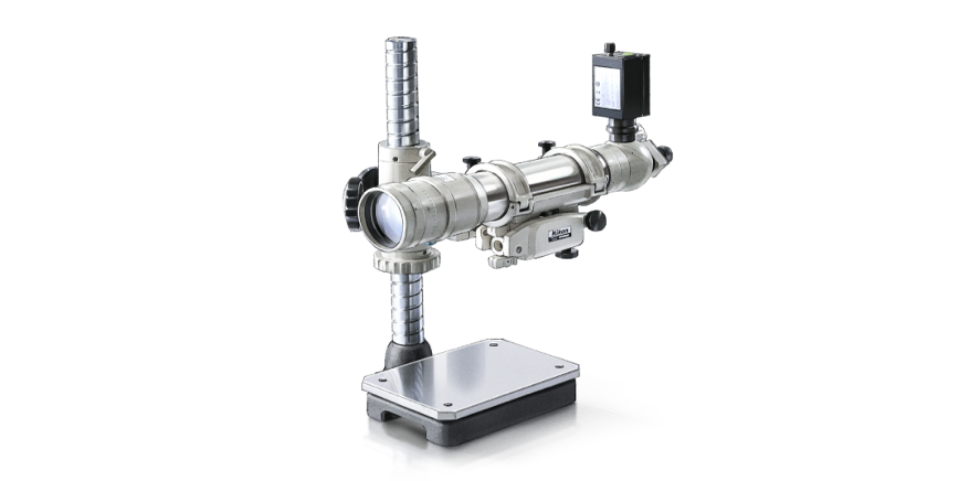
Fig. 3 Nikon autocollimator fitted with a digital camera (from Nikon online catalog)
Notice that ACs cannot be used without some auxiliary hardware because all they measure is departure from normal. As an example, assume the AC, mounted vertically looking downward, is zeroed out against a plane surface such as the base of the Nikon instrument. Then the AC measures parallelism when sample plane mirrors or windows are set on the base plane surface. They are also useful for measuring errors in prism angles where the faces of the prisms are parallel to each other looking through the prism.
Another instrument in this class is the alignment telescope (AT), an AC with more parts to give it more functionality. We use an AT to determine where an axis is or use it to set up an axis because the AT focuses in any plane between the instrument and infinity. This gives information to determine a line, 4 DOF, in space rather than just two angles.
I have used Fig. VIII from the 1957 Kueffel AT US Patent 2,784,641 in Fig. 4 to show the optically important parts. Starting at the left there is a Galilean 5:1 reverse beam expander and a meniscus element (714) which if decentered, decenters the field of view in the eyepiece, without changing the focus. This is followed by a Newtonian telescope (716) focused on a crosshair reticle that is projected from the AT. Following the reticle is a beamsplitter to bring in a light source, and an erecting eyepiece so the view is right side up when viewing thorough the telescope.
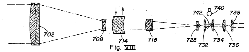
The objective (716) on the Newtonian telescope is used to focus the AT from very close to the front of the instrument all the way to infinity in an almost perfect straight line. Because the aperture and corresponding focal length are about 5 times smaller than the main objective (702), the distance the Newtonian objective must move to achieve this large focus range is very much reduced from moving the main objective.
As opposed to an AC, an AT determines 4 DOF, and thus an axis. It does so by first focusing on a far target, and then on a close target. When both targets are centered on the crosshair in the AT, the axis of the AT is coaxial with the line between the two targets. Making this adjustment is a little trickier than it first sounds. It is an iterative process, and the adjustments must be made in the right order, or you get farther and farther from alignment.
When focused on the far target, change the angle of the AT tube to bring the far target on the crosshair. When focused on the near target, translate the AT to bring the near target on the crosshair. Even following this order of adjustments, you are usually not rotating about the optimum center, so you end up either over or under-shooting the angle adjustment. With patience good alignment is achieved to the precision of the instrument and your ability to set the target on the crosshair.
Since this is a rather long blog, I will put off a discussion of the last instrument, the autostigmatic microscope until next week. I will also discuss a few mechanical gauges and tools that complement optical alignment tools.
For reference see:
https://www.vermontphotonics.com/electronic-autocollimators
https://trioptics.com/us/products/optitest-visual-measurement-instruments/
If I have overlooked anyone in this list, I apologize.