In the coming chapters, I will compare several methods of centering lenses where one degree of freedom is constrained. To keep things simple, all examples use a single plano convex lens with fixed tilt and decenter, assessed using a common measure of centering quality. The examples are presented in two dimensions, though the principles extend directly into three dimensions.
This chapter examines measuring edge thickness difference, or ETD, a mechanical centering method used long before optical test instruments became common. Subsequent chapters will cover image motion when a lens is rotated, as well as tracking a center of curvature either directly or by looking through the lens.
I will begin with background on ETD and its role in manufacturing and testing centered lenses. Next, we will look at reducing ETD when constrained by tilt or centration. I will then outline the model assumptions used to calculate alignment impact before concluding with the quantitative relationship between the optical and reference axes after alignment using ETD.
Much of this material has been addressed before, though not in a single overview using a unified characterization method. For further reading, Frédéric Lamontagne has written extensively on this subject across several SPIE papers and books.
Edge Thickness Difference (ETD)
Single lens elements are often made oversized in diameter and edged as a final step to align their mechanical and optical axes. Edge thickness difference is used to center the lens prior to edging and to verify axis alignment afterward. While rarely used for small lens assemblies, this technique is applied to large optics, including elements nearly a meter in diameter for lithography lenses.
Edge thickness difference operates on the same principle as cup edging machines, where a lens self-centers between two coaxial cups brought together from opposite sides as in Fig. 1. Material not concentric with the axis is edged off as the lens is brought to finish diameter.
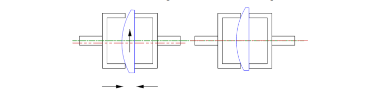
Fig. 1. Initially wedged lens inserted between the two cups (left) and becomes centered as the cups squeeze the lens to equalize the thickness at the edge, making axes coincident.
An initially decentered lens makes contact at one edge first due to the difference in thickness. As the cups press together, they shift the lens until the edge thickness is equalized, making the optical axis coaxial with the centerline of the cups. Fig. 1 uses the ISO 10110-1 standard designation of a mechanical axis or centerline as a dot-dash line, and an optical axis as a dot-dot-dash line.
Measuring Edge Thickness Difference
Before cup edgers, lenses were checked for centration using a dial indicator and a fixture that defined five degrees of freedom. Three small balls constrained lens tilt by supporting one surface, while two larger balls constrained centration along the outer edge as shown in the perspective view in Fig. 2.

Fig. 2. Five-constraint fixture for measuring ETD with an indicator tip (red ball).
The three small balls fix the location of the lower surface center of curvature, while the larger balls define the mechanical center. A dial indicator tip (the red ball) measures the height of the upper surface near its edge. The operator inserts the lens into the fixture, rotates it against the larger balls to find the maximum or minimum indicator reading, turns the lens 180 degrees, and repeats the measurement. The difference between the two readings is the ETD.
A lens with wedge as in Fig. 3 shows a height change under the indicator after an 180° rotation. Assuming the measurement is taken at the outer edge, the wedge angle relates to ETD by dividing the thickness difference by the lens diameter.
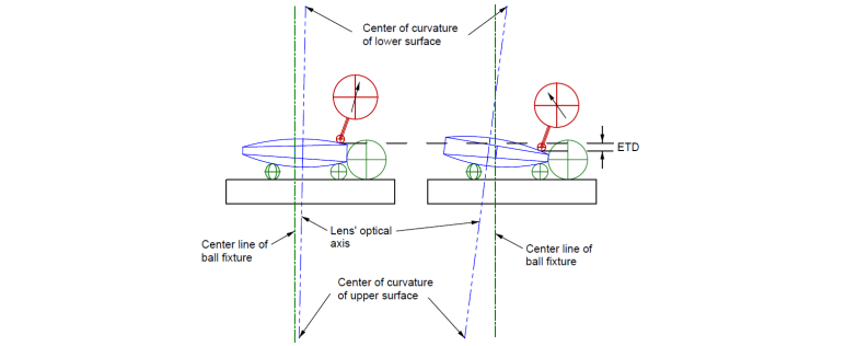
Fig. 3. Lens with wedge being measured for ETD at maximum and minimum thicknesses.
The lower surface center of curvature remains stationary relative to the fixture centerline during rotation because the three small balls fully constrain it. This mimics a lens resting on a circular seat in a cell. Conversely, the upper surface center of curvature shifts during rotation if the optical axis is displaced from the mechanical center.
Measuring ETD does not require exact fixture sizing to the lens diameter, provided the indicator tip stays near the edge for maximum sensitivity and the lens remains properly supported. For a lens free of wedge, the lens’ optical axis and the fixture axis defined by the balls will be parallel and only be coincident if the lens diameter exactly matches the fixture design. This aspect of the fixture design is explained in more detail in the next chapter.
Optical Centering by Measuring Reflected Light Slope
Centering can also be done by directing a beam of light at an unconstrained lens surface as in Fig. 4. If the ETD is zero, the reflected beam remains stationary as the lens rotates. Prototype optical shops often use this method by mounting a lens on a single true running cup using wax or vacuum and tapping the edge of the lens to adjust it until the reflected spot stops moving during rotation.
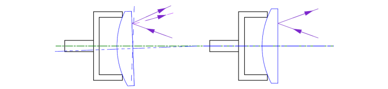
Fig. 4. Lens mounted on single cup edger, misaligned (left) where the dotted line shows the surface rotated by 180 degrees, and aligned (right) where the reflected spot is stationary.
Achieving a zero ETD is equivalent to viewing a stationary reflected beam on an axis coaxial with the optical axis as in Fig. 5. A spherical surface yields no indicator movement or beam deflection if rotated about an axis passing through its center of curvature. However, the optical and rotation axes must be strictly coaxial for the ETD to vanish entirely.
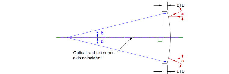
Fig. 5. Shows the equivalence of a vanishing ETD and the stationary nature of a reflected beam off a lens surface.
Model Parameters and Alignment Conventions
To compare centering methods quantitatively, we use a plano convex lens with a 100 mm effective focal length, a 50 mm convex radius, a 4 mm center thickness, and a refractive index of 1.50 shown in Fig. 6. The first nodal point and optical center [1] reside at the first surface, which serves as the axial origin. The second nodal point sits at 1.333 mm, and the apparent center of curvature after refraction through the plano surface is at 34.286 mm. Both optical and mechanical centers of curvature lie on the optical axis.
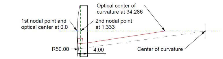
Fig. 6. Parameters of the model plano convex lens used for the centering calculations.
In a perfectly centered lens, the optical and mechanical axes coincide, making it difficult to show in the Figures, so we use only one axis in this case. For the reference axis, which is used for ray tracing, we use a dashed line.
We evaluate two specific initial misalignments: a 1 milliradian tilt and a 0.1 mm decenter. A 1 milliradian tilt corresponds to the plano side resting on a seat tilted relative to the reference axis, with adjustment restricted to sliding along the seat. A 0.1 mm decenter corresponds to an offset seat, with the adjustment restricted to rotating the lens about its center of curvature, which simultaneously changes tilt and decenter. Fig. 7 shows these misalignments prior to correction.
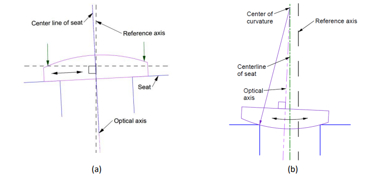
Fig. 7. The two alignment situations considered, (a) where tilt is constrained, and (b) where decenter is constrained by the seat.
Quantitative Effects of Alignment Constraints
Correcting the tilted lens requires sliding it along the seat until the upper surface center of curvature lies on the reference axis, which brings the ETD to zero. Correcting the decentered lens requires rotating it about its center of curvature until tilt is eliminated, which zeroes the ETD but leaves the lens offset from the reference axis because the seat is decentered from the reference. Fig. 8 shows the lens after these two corrections are made using a zero ETD.
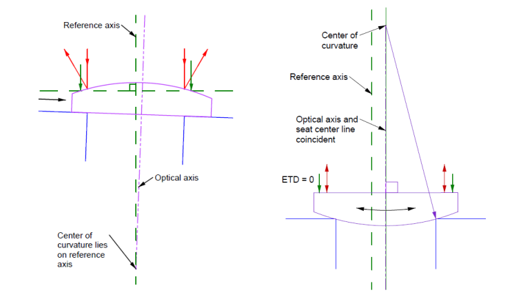
Fig. 8. Tilted lens with misalignment corrected by decentering (a) and decentered lens with misalignment corrected by rotating about its center of curvature (b).
In the tilted case, Fig. 8a, the initial 1 milliradian tilt displaces the center of curvature at 46 mm distance by 46 micrometers from the reference axis. Decentering the lens by 46 micrometers restores zero ETD. A ray entering along the reference axis exits at a height of 1.33 micrometers and an angle of 487 microradians. This matches first-order predictions for a 4 mm thick plate tilted by 1 milliradian and a thin prism with 1 milliradian of wedge. Here, the optical and reference axes intersect at the center of curvature.

In the decentered case, Fig. 8b, zero ETD occurs when the plano surface is parallel to the seat, leaving the entering ray parallel to the optical axis but displaced by 0.1 mm. The ray exits at a height of 97.33 micrometers and an angle of 1 milliradian, matching expectations for a 97.33 mm back focal length. The ray travels parallel to the optical axis until the second principal plane, then refracts toward the focal point. In this scenario, the optical and reference axes remain parallel.
To summarize, using ETD to center a tilted plano convex lens leaves an entering ray exiting at 1.33 micrometers and 487 microradians, with the optical and reference axes intersecting at the center of curvature. Centering an offset lens with no tilt leaves the exiting ray at 97.3 micrometers and 1 milliradian, with parallel axes.
The next chapter will evaluate centering via image motion of transmitted light and address remaining details from this analysis.
Acknowledgement: I acknowledge the help of Reid Greenberg for reading the first draft and pointing out several items to clarify. I also acknowledge Gemini for cleaning up my final draft. I still had to make a few small tweaks, but overall, I was impressed with the result for clarity and succinctness.
[1] R. Barry Johnson, “Correctly making panoramic imagery and the meaning of optical center,” Proc. SPIE, 7060: 70600F (2008).