ABSTRACT
Although the PSM is primarily an alignment instrument, it can also be used to determine the conjugates of parabolic and elliptical off-axis mirrors. By positioning the PSM at the sagittal and tangential foci of the mirrors, the conjugate distances of the mirror can be found using a laser range finder, for example. Knowing the sagittal and tangential radii of curvature (Rs and Rt), the vertex radius (Rv) is easily calculated. This information is used to verify that the mirror has been correctly manufactured and to aid in positioning the mirror in an optical system. Examples are shown of these steps.
1. INTRODUCTION
The alignment of off-axis aspheres is a subject that few people want to address because it is so different than aligning symmetric optics. An off-axis asphere has an optical axis, as opposed to a sphere that has no optical axis, just a center of curvature. Furthermore, the optical axis of the off-axis asphere usually does not pass through the surface of the mirror and certainly is not parallel to the normal to the surface at the center of the off-axis segment. On the other hand, off-axis aspheres are extraordinarily useful for many optical designs, and familiarity with them is essential for many optical systems.
This paper is an attempt to take some of the mystery out of off-axis parabolas and ellipses in terms of their geometry, and how to use their geometry to aid in their alignment. We will start by discussing some of the geometry that makes off-axis mirrors unique, and then describe how to find and measure the conjugates that are analogues to the center of curvature for a sphere. As opposed to a sphere with a center of curvature, an off axis asphere has two conjugates that define its axis, the two astigmatic foci at the centers of curvature of the tangential and sagittal radii of curvature. With the knowledge of how to find these conjugates, and a method of measuring the radii of curvature, it is possible to see that the mirror was manufactured correctly, and to see how the mirror should be aligned into the optical system for which it is intended.
2. GEOMETRY OF AN OFF-AXIS PARABOLA
Fig. 1 is a scale drawing of an off-axis parabola looking at a meridional section and along the optical axis (black vertical line). The off-axis section is the circle at the right edge of the pie section looking along the optical axis. It is aligned with the three vertical lines that defined the inner and out meridional extents of the off-axis section. The parent parabola is green and the blue circle has a radius equal to the vertex radius of the parabola while the purple circle segment, whose tangential radius is labeled Rt, is the best fit circle to the center of the off-axis segment. The light blue rays stopping at the optical axis define the sagittal radius of curvature, Rs.
The three radii are related by Rt = Rs^3/Rv^2 which makes it easy to find an unknown radius if the other two are known1. If a point source of light is placed on the axis of the parabola, a line image will form at the axis (light blue line perpendicular to the Rs ray). In general, the image will not be a line until the aperture of the off-axis section is masked, or stopped, down to a diameter where the coma in the off-axis asphere does not affect the astigmatism. How big a hole in the mask can be determined empirically, or an estimate of the coma may be made referring to Ref. 2.When the point source of light and the return line image are superimposed, the point source is on the normal to the surface at the center of the hole in the mask. The distance from the surface to the point source/line image is the sagittal radius, Rt. The astigmatic line image will lie in the meridional plane and is helpful in determining the azimuth of the vertex of the offaxis segment as well as determining the sagittal radius.
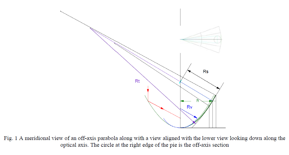
If the point source of light is moved back along the normal until the astigmatic line image is in focus it will be seen to be perpendicular to the meridional plane. The distance from the point source/line image here is the tangential radius, Rt. Since Rs = sqrt(Rv^2 + h^2) where h is the off-axis distance it is easy to find h.
3. GEOMETRY OF AN OFF-AXIS ELLIPSE
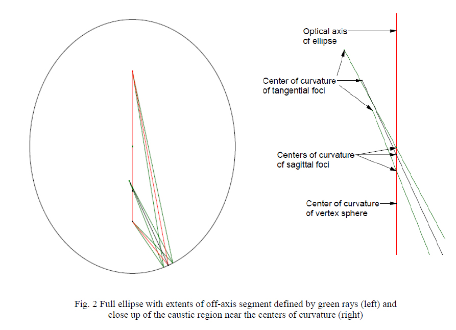
The geometry of an off-axis ellipse is a little more complex but the same basic geometry applies. Fig. 2 is a scale drawing of one of the parts we actually measured using the PSM and FARO arm. The green rays show the extent of the off-axis section relative to the foci to give a feel for the scale. The rays that bisect the rays going to the foci are those seen from the center of curvature of the off-axis segment. The right side of Fig. 2 shows the caustic region to give a better idea of the locations of the sagittal and tangential centers of curvature relative to the center of curvature of the vertex sphere.
As with the parabola, the sagittal foci lie on the axis of symmetry, or optical axis, while the tangential foci lie of the far side of the axis. From the way an ellipse focuses light from one focus to the other, we know the normal to the surface is the perpendicular bisector of the rays between the foci as shown. Just as with the parabola, we can find Rs and Rt, and using these values we can find Rv = (Rs^3/Rt)^1/2. For the ellipse we still need to find the conic constant, k, and the distance off-axis, h. To do this we make a mask as in the case of the parabola and measure Rs and Rt at 2 or 3 locations, h and ±delta h, where delta h is known. Two measurements will give an exact solution, while 3 or more will give a least squares solution using the relation that Rv^2 –k*h^2-Rs^2 = 01. The simplest method is to use 2 measurements at either edge of the off-axis ellipse and find the solution using the quadratic equation. One thing to remember is that delta h measured off the optic will be larger than it actually is, the distance from the axis of symmetry. Entering delta h as 1.4x less than the width of the optic is probably a good guess for a start.
Clearly with a concave ellipse this approach will get you close because the foci have to lie on the same line, the optical axis, as the sagittal foci. Also, for any given h, the line joining Rs and Rt lies on the normal to the surface. This will help locate the foci approximately. With this information it is then more precise to try to find the foci directly using the information derived from Rs and Rt. Using a point source such as the end of a single mode fiber at one focus and a microscope at the other focus it should be possible to locate the 2 foci to the precision necessary to meet system tolerances.
4. MEASURING THE SAGITTAL AND TANGENTIAL RADII
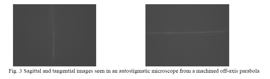
Using an autostigmatic microscope such as the PSM3, point the microscope at the mirror and locate the return image. Once the microscope is adjusted so the reflected point source is centered on the objective, focus the microscope to find either the sagittal or tangential focus. In general the reflected image will be too blurred to find a clean line image. Mask the mirror with an aperture small enough to produce a line return image. Adjust focus to get clean looking images such as that in Fig. 3.
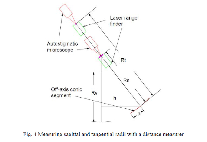
When the microscope is well focused, bring a distance measuring device such as a laser distance measurer, or laser range finder4, up in front of the microscope and position it axially to get a focused Cat’s eye reflection off the rear of the distance measurer. Then take a distance reading to the mirror through the hole in the mask. Since most distance measurers calculate the distance from the rear surface of the instrument, the measurer reading is the sagittal or tangential radius, depending on which image is in focus. Fig. 4 shows how the measurement is made schematically.
Once these measurements have been made, the results may be compared with the prescriptions for the off-axis segments to see if the manufactured mirrors are to specification using the equations in the first part of the paper. It turned out in our case that one mirror was in spec and the other was not. Luckily it turned out that the specification was tighter than it needed to be and the mirror did not limit the performance of the system.
Once these measurements have been made, the results may be compared with the prescriptions for the off-axis segments to see if the manufactured mirrors are to specification using the equations in the first part of the paper. It turned out in our case that one mirror was in spec and the other was not. Luckily it turned out that the specification was tighter than it needed to be and the mirror did not limit the performance of the system.
5. USE OF THE SAGITTAL AND TANGENTIAL FOCI FOR ALIGNMENT
There are at least two ways the focus information can be used for the alignment of off-axis mirrors. First, the measurements can be used directly by adding alignment features to the optical bench that the mirrors will be installed in. Since the two foci produce line images in reflection, we can use polished cylindrical artifacts to simulate the line foci. An inexpensive source of suitable artifacts are “plug gauges”5, cylinders about 50 mm long in diameters ranging from <1 mm to 25 mm or more. These are used the same way polished balls are as physical realizations of points to focus a PSM on, but in this case the cylinders are realizations of lines. Kinematic mounts should be made so 2 plug gauges are positioned where the sagittal and tangential foci are supposed to be located in the finished mirror system.
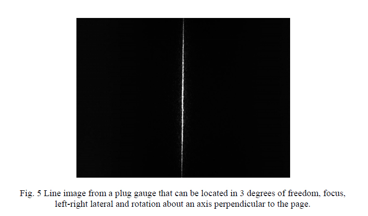
To align an off-axis segment, a PSM is focused on the line image formed at the axis of the plug gauge, the gauge is removed and the mirror adjusted so its focus appears in the same location as the line formed by the plug gauge. Fig. 5 shows a typical image on reflection from a plug gauge. The mirror can be located in 3 degrees of freedom, axially, one degree of translation, and one degree of rotation about the normal to the mirror surface. Once one focus is adjusted, the PSM is moved to the second plug gauge, and focused on it. The gauge is removed and the mirror adjusted by rotating around the first focus until second focus is correctly positioned laterally. This process may take some iteration because it may be difficult to make the mirror rotate around the first focus although with sufficient forethought the mirror mount could be designed with this adjustment built in.
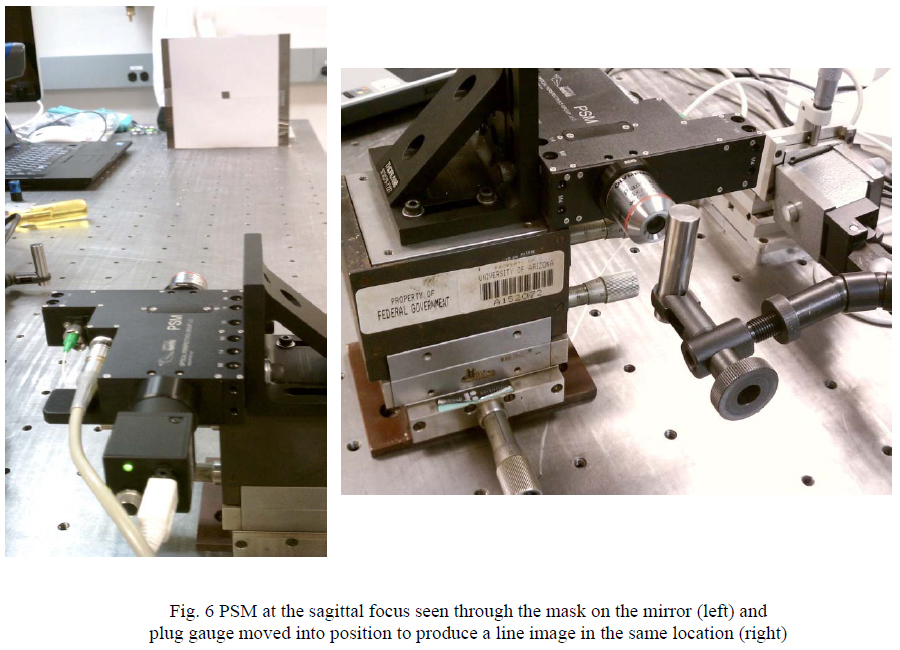
A second method of alignment, an indirect one, is what we did. We located plug gauges at the two foci and then measured the locations of the gauges relative to fiducials on the mirrors. Fig. 6 shows how a plug gauge was adjusted to be at the same location as the line image formed by the mirror sagittal focus, in this case. This meant that when the mirrors were installed in their optical bench using the fiducials around the edges of the mirrors, we were effectively positioning the foci to their correct positions in space.
6. RESULTS OF MEASUREMENTS ON AN OFF-AXIS MIRRORS
The mirrors we measured were about 250 mm square and CNC machined out of 6061-T6 aluminum and then smoothed and polished by hand to a specular surface. One of the mirrors is seen behind the mask in the left hand part of Fig. 6. The ultimate use did not require the polish as they are to go in a terahertz wavelength (857 μm) radio telescope. On the other hand, we wanted to be sure the mirrors were sufficiently good to meet the telescope spec, and had been correctly machined and not deformed by the polishing.
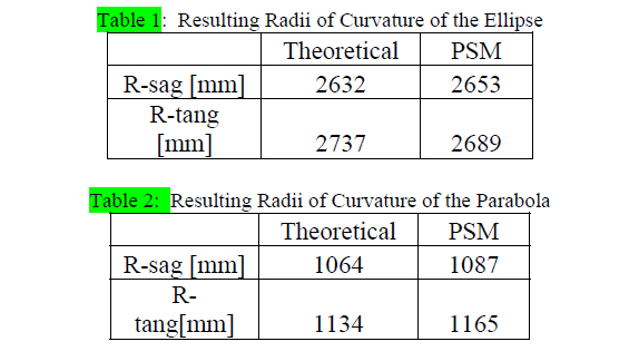
Following the procedure described above we got the results shown in Tables 1 and 2. The standard deviation in terms of setting at the best focus of the line focus was about ±4 mm for the parabola and ±10 mm for the ellipse. The distance measuring laser gauge gave consistent readings within ±1 mm. Thus both mirrors had larger errors in their radii than could be attributed to measurement error. On the other hand, the radius errors amount to sag errors over the full aperture of 30 and 50 μm in the case of the ellipse, and 160 and 190 μm in the case of the parabola, compared with λ = 857 μm.
After reviewing these errors in manufacture in the optical design code it was felt that with a minor spacing adjustment the mirrors would work just fine as they were. This finding coupled with the knowledge of where the fiducials were relative to the radii of curvature meant that the system would perform as expected and could be successfully aligned.
7. CONCLUSION
We have shown how to determine the vertex radius of curvature and off-axis distance of off-axis parabolas by measuring the sagittal and tangential radii of curvature with an autostigmatic microscope such as the PSM. We have gone on to show how the conic constant may be determined as well by making multiple measurements of the radii of curvature for more general conics. This information is useful as part of incoming inspection to see if the optics ordered are the optics delivered. Further, we have shown how the locations of the radii of curvature can be used as a tool in aligning the offaxis mirrors into their optical systems using two different approaches to alignment.
REFERENCES
- Smith, W., Modern Optical Engineering, 2nd Ed., McGraw-Hill, New York, 445-6 (1990)
- Parks, R. E., Evans, C. J. and Shao, L., “Test of a slow off-axis parabola at its center of curvature”, Appl. Optics, 34, 7174-8 (1995).
- See www.optiper.com
- For example, see https://www.cpotools.com/bosch-dlr130k-digital-distance-measurerkit/ bshndlr130k,default,pd.html?start=1&cgid=bosch-locators-and-measurers
- See, for example, https://www.mcmaster.com/#plug-gauges/=dbxtba