1. Introduction:
Laser trackers are an accurate and efficient tool for finding the locations of features in a threedimensional space but they rely on Spherically Mounted Retroreflectors (SMR) to return the laser beam to the tracker. If the feature cannot be contacted or it is not convenient to use an SMR another method must be used to follow the beam. We describe methods using a dual imaging and autostigmatic microscope for locating the features and two methods for tracking the microscope location depending on the type of tracker used. This converts a contact probe, large area CMM into a non-contact CMM by coupling a laser tracker with a dual purpose autostigmatic microscope. We begin with a brief description of the microscope followed by the alignment of the microscope to tracking and scanning laser metrology stations.
2. Point Source Microscope:
The imaging, autostigmatic microscope in question is called a Point Source Microscope (PSM)1 and has both a single mode fiber as a point source of light for the autostigmatic function and a LED behind a diffuser to provide Kohler illumination for imaging. The sources may be used independently or simultaneously. In the autostigmatic mode the PSM has lateral sensitivity of <1μm and similar axial sensitivity with an auxiliary lens for finding the centers of curvature of tooling balls or optics like mirrors and lenses. In the imaging mode the lateral sensitivity depends on the objective used but is in the neighborhood of a couple microns and the Cat’s eye reflection from a surface gives axial sensitivity to a similar resolution. It remains to show how to couple this non-contact ability to locate centers of curvature, the optically important feature of a lens or mirror for alignment purposes, to a high level of sensitivity to laser tracker systems that can determine locations in 3-dimensional space to similar sorts of accuracies.
3. Follower type laser tracking systems:
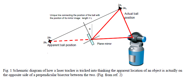
A follower type laser tracker is similar to a surveyor’s theodolite but is more sophisticated in that it is active. It sends out a laser beam along the telescope axis and the telescope will follow the beam if it is retroreflected back using a corner cube (generally a SMR that has the feature that the apex of the cube corner is accurately located at the center of the ball or spherical mount). The tracker will also measure distance using an interferometer mode if the SMR is moved from the tracker calibration SMR nest to a nest mounted on the measurand without breaking the laser beam. Fig. 1 shows how the follower tracker scheme works in general.
3.1 Alignment of the PSM to an SMR:
SMR’s are made in several convenient sizes, ½”, 7/8” and 1½” diameters, along with corresponding SMR “nests”, usually steel cones with a magnet at the apex to hold the SMR seated in the cone. A nest and corresponding SMR are mounted at a convenient location and the tracker is locked onto the SMR and its location in 3-D is noted. The SMR is removed from the nest and a grade 25 or better steel ball of the same diameter is placed in the nest so that its center is in the same location as the SMR. Then the PSM is adjusted so the focus of the objective is located at the ball center, something that can be done to <1μm in all three dimensions.
3.2 Alignment of the tracker to the PSM:
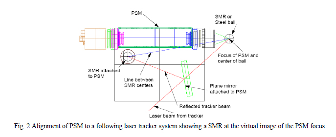
Attached to the PSM is a plate with a plane mirror in a mount that can be adjusted in tip, tilt and piston and a nest and an SMR. The plane mirror, shown schematically in Fig. 1, is nominally located half way between the objective focus and the SMR on the plate and perpendicular to a line between the focus and SMR. This arrangement is shown in Fig. 2. The mirror reflects the tracker laser beam back toward the SMR on the plate. The plane mirror is adjusted until the reflection from the SMR on the plate has the same apparent location as the SMR originally located at the PSM focus. The mirror is then adjusted such that the tracker sees the virtual image of the SMR at the objective focus. Now the assembly of PSM, plane mirror and SMR can be moved at a unit and the tracker will follow the PSM focus in all three dimensions as long as the PSM is not rotated so far that the tracker laser beam walks off the plane mirror.
4. Scanning type tracker system:
A scanning type tracker system uses several high speed rotating prism stations to sweep line images around a workspace. The prism scanners are accuracy synchronized with a clock. In the work space are detectors that resister when a beam sweeps by. Comparing the prism clocks and detector signals the detector locations can be accurately determined by time delay triangulation.
4.1 Alignment of the detectors to the PSM:
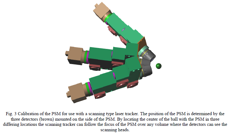
With the scanning system, three detectors are fastened to the side of the PSM facing two scanning prism stations. The PSM is focused on the center of a conveniently located steel ball. In this position the detectors are scanned by two scanning stations a known distance apart. Since three detectors on the PSM are scanned the plane of the detectors is determined relative to the scanning stations. The PSM with detectors attached is then moved to a different orientation while still being focused at the center of the ball and another set of data is taken to determine the plane of the detectors. This operation is repeated for a third orientation of the PSM while the PSM is centered on the ball. The three planes defined by the detectors will appear to rotate about the center of the ball, that is, a normal to each of the planes through the center of the ball are all equidistant as shown in Fig. 3.
This means the center of the ball, or focus of the objective, can be determined from the three measurements and once the distance from the center to the planes of the detectors is determined and recorded, any other position of the PSM can be related back to the center of the ball. This calibration is completely analogous to the initial use of a master ball and a touch probe on a Coordinate Measuring Machine (CMM) to establish the zero of the CMM coordinate system.
4.1.1 Using the calibrated PSM:
Once the center has been determined by this calibration, when the PSM is moved to any other location and the positions of the three detectors determined the location of the focus can be related to the center of the ball in all three coordinate directions. Any software that might be used with a CMM can also be used to analyze the data the scanner tracker gathers. This makes it possible to use the PSM precisely as a non-contacting probe with an apparent zero probe tip radius for any sort of coordinate measurements over large distances.
5.0 Conclusion:
We have shown how an autostigmatic microscope, and in particular, the Point Source Microscope (PSM) as a non-contact probe, can be used with laser tracker systems, either the follower type or the scanning type. In the first case an auxiliary mirror and tracker ball are used to make the tracker think it is looking at the focus of the PSM. In the second case, the PSM is calibrated in a way analogous to using the master ball on a CMM and then the PSM can be used as a zero radius probe tip for non-contact coordinate measurements over large distances. In both cases the PSM can be used either to find a center of curvature to 1 micron sensitivity in three dimensions or used in the imaging mode to locate a feature on a surface to 2 o3 microns in all three dimensions. The fact that the PSM images and can be set in all three coordinates to micron precision makes it a valuable part of an extension to contacting laser tracker systems.
6.0 References
1. Optical Perspectives Group, LLC, Tucson, AZ 85750, www.optiper.com.
2. J. Burge, et. al., Use of a commercial laser tracker for optical alignment, Proc. SPIE, 6676, 6676OE, (2007).