In this Chapter we will discuss the centering of a single center of curvature of a lens in a cell sitting on a rotary table that creates a reference axis. This discussion describes the traditional method of centering a lens in a cell. While this does not sound like an ambitious goal, the ideas presented here set the context for all the alignment topics to follow. We will get into much more complicated situations later, but it makes sense to walk before we run so that we understand the principals involved.
A rotary table was used for centering long before anyone heard of optics. Rotary tables, lathes or bearings are used to make objects that have no variation in the normal distance from the axis of the table as the table is rotated. If there is a method of measuring the height variation, we say the object is round and centered when no variation in height is observed normal to the axis of rotation by a fixed indicator or measuring device.
Notice there are two assumptions, one implicit; the object must be round, no azimuthal height variation and implicitly, the bearing true. The proper combination of a non-round object and poor bearing behavior can make it look like the object is centered. We will assume we have a perfect bearing so that any motion observed that is synchronous with the table rotation indicates decentration. This also implies that our centering will never be better than the bearing precision in tilt and decenter.
Using a rotary table introduces a practical constraint. In most cases the axis of the table is vertical so that gravity works for us. There are many examples where this is not the case, but for centering during the assembly of optics it is almost universally the case. The optical instrument, or sensor, viewing the optics being centered is mounted on a vertical slide centered on the axis of the rotary table. A scale to measure the height of the sensor that has a resolution consistent with the precision of the spacing of the lenses in the cell completes the hardware as shown schematically in Fig. 1
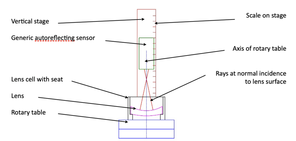
Fig. 1 Schematic diagram of a rotary table lens centering apparatus
The viewing, or sensing, instrument projects a point source of light, or an illuminated reticle, toward the lens being centered. When the projected source is at the center of curvature the light is normally incident on the upper concave surface and reflects back to the focal plane of the sensor and into an eyepiece or onto a monitor screen for viewing. As the rotary table revolves the reflected image will precess synchronously with the table unless the center of curvature is precisely aligned to the rotational axis of the table. The reflected image may not lie on the axis of the sensing instrument, but this only means the sensor in not well aligned to the axis of the table. If the image is stationary, it is on the axis of the rotary table. Fig. 2 helps with this explanation.
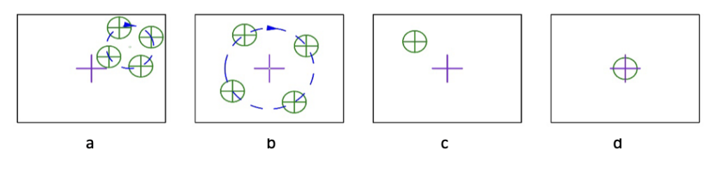
Fig. 2 Four possible alignment situations as the rotary table rotates the lens in Fig. 1
(The purple cross is the origin of coordinates within the sensor field of view, the black outline)
In Fig. 2a the center of curvature of the lens is not on the axis of rotation of the table nor is the sensor centered with respect to the table. In Fig. 2b the center of curvature is not centered on the table axis but the table axis is aligned with the coordinate origin of the sensor. In Fig. 2c the lens center of curvature is centered on the table axis because there is no motion as the table rotates but the axis of the table is not centered with the sensor origin, while in Fig. 2d the lens is centered and the table axis is centered with the sensor. In either case 2c or 2d the lens is centered with respect to the rotary table axis and that is all that is necessary for this one conjugate to be perfectly centered. That the reflected image does not lie on the center of the sensor has no effect on the centration of this surface of the lens.
When the reflected image precesses with the table, then the center of curvature does not lie on the axis of the rotary table as in Fig. 3a. There are 2 ways to move the center of curvature onto the table axis. Referring to Fig. 3b, we can decenter the cell and lens pair until the image is still. Alternatively, we can rotate the lens about the center of curvature of the surface sitting on the seat as in Fig 3c and decenter the cell to keep the lens from interfering with the cell. Either method, or a combination of the two will center the image, but this does not mean the optical axis of the lens (magenta dotted line) is concentric with the axis of the table, only that the center of curvature of the upper surface is coincident with the axis of the table at a single point. Only when the cell is centered, and the lens rotated about the center of curvature of the surface against the seat are the 2 axes coincident. There must be sufficient clearance between cell and lens to make up for centration errors during edging the lens or the lens hits the cell, 2d.
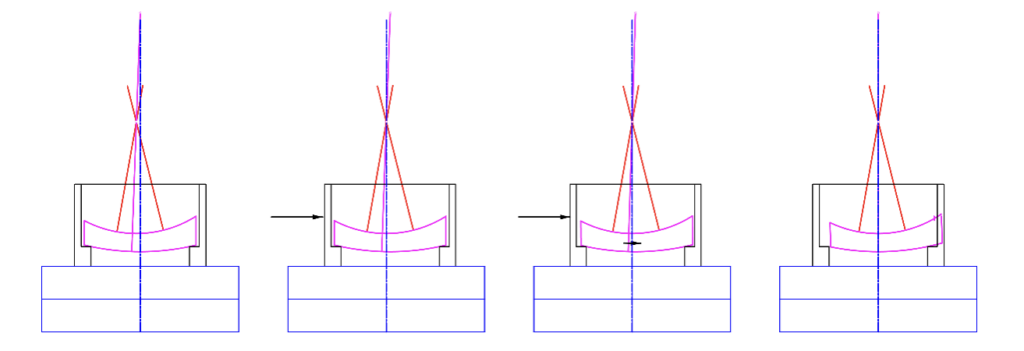
Fig. 3 With center of curvature not on the table axis (a), and on the axis (b, c and d)
Since we are only looking at one reflection for the moment, is there a way of completely centering the lens in Fig. 1 in the sense that it is free of tilt and decenter relative to the rotary table axis? Fig. 2d suggests that if we break the alignment into two parts, the answer is yes. First, we get the seat centered to the table axis using either mechanical or optical means. The centered seat and cell are locked to the table and the lens inserted. Since the seat is centered on the axis of the table, the surface of the lens sitting on the seat must also be centered.
To finish centering the lens we must tap the edge of the lens to tilt it in the seat until the reflection from the center of curvature of the upper concave surface remains stationary as the table rotates. The axis of the lower surface remains on the axis due to the mechanical interface between the lens surface and the seat while the upper surface is free of tilt via the optical reflection.
As a bit of a sidebar, this technique that separates the operations of removing decenter separate from tilt orthogonalizes the centering. A derivative of this method is called mounting lenses in poker chips or bond rings. These mounts are accurately parallel with seats parallel to the outer surfaces. Jump ahead to Fig. 4a to see what a bond ring with a convex lens might look like. Notice that the convex surface center of curvature will always lie on the axis of the bond ring. Tilting about the center of curvature of that surface will bring the center of curvature on the axis of the bond ring if there is clearance.
Assuming the surface of the rotary table is precisely normal to the axis of rotation and the seat of the bond ring centered, the lens can then be inserted and made tilt free as above by using a reflection from the center of curvature of one or the other surfaces. The optical axis of the cemented bond ring/lens pair is then precisely normal to the parallel faces of the bond ring. If all the lenses in an assembly are prepared in the same way, then the whole assembly is aligned by simply removing decenter as each addition element is added to the assembly. This method is often used to assembly the lens elements in large lithographic systems, and a close analog is used to assemble microscope objectives.
Whenever precise centration is needed in a lens system the bond ring approach should be considered. It gives the necessary adjustment needed to correct for both tilt and decenter while not having the procedure of adjusting for one upset the other. The adjustments are separate and orthogonal. The method does involve extra metal parts, but these additions are generally more than offset by ease and precision of assembly. Also, a design may only have one critical interface as far as alignment goes. Use the bond ring idea only where it is necessary,
To finish up this discussion, look again at Fig. 3. When adding the second lens to the assembly we must assume the seat is not completely concentric to the rotary axis. This means that when we attempt to center the lens, we only have the option to tilt the lens to center it. There is nothing we can do about the decenter. This leaves the question of what is the best tilt for optimum performance of the lens system. Currently in our discussion there is nothing to do but tilt the lens until the center of curvature is stationary. In a later chapter we will show there may be a better option for best centering.
There are analogous situations where the only option is to decenter the lens as in Fig. 4b when the interface is a flat on the lens, the usual situation when the curve is concave. Here it is impossible to tilt the lens if the flat is not perpendicular to the optical axis of the lens. The only way to correct for centration is to decenter the lens. In Fig. 4b this will largely correct for the wedge error in edging but not completely since the axes of the cell and lens are not parallel. These two situations point out the connections between the tolerancing of the cell and the lens. If the mating surface to a convex spherical surface is a seat as in Fig. 4a then the seat concentricity limits the centering of the lens. If the lens sits on a flat seat as in Fig. 4b, then the lens must be precisely edged to assure the flat is perpendicular to the optical axis of the lens. The cell seat centration is not important, but it must be perpendicular to the cell axis.
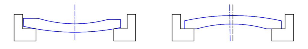
Fig. 4a Lens with a convex surface sitting on a bond ring seat with the concave surface perfectly centered by tilting the lens in the seat, and Fig. 4b where the lens sits on a flat seat and decenter is the only possible centration correction which will not completely work because the axes are not parallel
With these thoughts about tolerances in mind let me recommend the recent book by Herman, Aikens and Youngworth, “Modern Optics Drawings: The ISO 10110 Companion” published by SPIE. Because the optical drawings on centering in Chapter 8 all have to do with making and inspecting lenses as mechanical parts, virtually all the discussion is about mechanical methods of inspection and tolerancing.
This is just the area where many optical designers are unfamiliar with the techniques used to inspect optical elements. The book has numerous examples of how the tolerances on the drawing relate to the mechanical centration properties of the lenses and the mechanical methods of measuring them.
Hopefully I have given you an introduction to optical methods of verifying these measurements by making slight changes to the concepts in Figs 3 and 4. This introduction is hardly complete and in later Chapters we could revisit how to optically verify that lens elements meet the tolerances on drawings. Again, I highly recommend the book on the ISO drawing standard. It is used internationally and most optical drawings these days follow the ISO standard.