In the previous chapter we looked at finding a single center of curvature using any of several optical instruments. This locates a particular point in space but does not define an axis. For that, two centers of curvature separated by a finite axial distance must be located to define an axis, or line. This chapter is devoted to finding an axis based on locating two centers of curvature simultaneously.
We resume with the assumptions from the previous Chapter that we have a rotary bearing table with its axis vertical and our optical sensor centered on the axis of the table looking downward at the table as was shown in Fig. 1 of Chapter 6. The sensor must be mounted on a vertical slide moving parallel with the table axis to reach the two centers of curvature.
(Sidebar – Presumably an alignment telescope could be used to view the centers of curvature by adjusting the focus knob rather than moving the instrument along a vertical stage. Because of the mass, size and lack of video cameras I have never seen a rotary table centering instrument built using an alignment telescope. There may be such a configuration but I am unaware of it.)
This situation presents us with our first alignment task, the vertical slide needs adjustments in angle and position so the viewing instrument it carries moves parallel the axis of the rotary table as it is raised and lowered. To do this alignment optically we need an optical element sitting on the rotary table that has two separated but accessible centers of curvature along its optical axis. The BK7 element 10 mm thick shown in Fig. 1 is an example of an element that will work to produce the two centers of curvature.
Obviously, there will be a reflection 100 mm from the concave side. Looking into the concave side, the 175 mm convex surface looks like its center of curvature is about 249 mm above the concave surface giving 2 spots 149 mm apart, good enough to discern the angle of the vertical slide to about 1 second of arc when we measure the centers of curvature lateral position to +/- 1 µm precision.
Fig. 1 An optical element with 2 easily accessible conjugates to use to find the axis of a rotary table
You do not need a lens design program to do the calculation for a single element. If the left hand surface is R1 then its apparent center of curvature looking into R2 is R1optical = -R2(R1-t)/((R1-t)(n-1)-nR2) = 248.52 mm where n for BK7 at 640 nm is about 1.517. For more complex systems, a 1st design spreadsheet is very useful, and we will talk about some tricks to use with 1st order design in a later Chapter.
The two centers of curvature are easily viewed with either an autostigmatic microscope, or an autocollimator with an auxiliary objective of a suitable working distance. The element in Fig. 1 that you want to center is sitting in a seat that has adjustments for centering the seat relative to the table axis. With R1 sitting on the seat, the center of curvature of R1 will lie on the axis of the seat because a circle of any radius less than the radius of the sphere will lie on the surface of the sphere with the normals to the center of the circle passing thorough the center of curvature of the sphere as I have tried to indicate in Fig. 2. Thus, tapping the edge of the element in Fig. 1, or red circle in Fig. 2, will tilt the lens about the center of curvature of R1 and the center will never move off the axis of the seat. The idea in Fig. 2 is obvious but just because it is obvious is often overlooked. The concept is very important to centering.
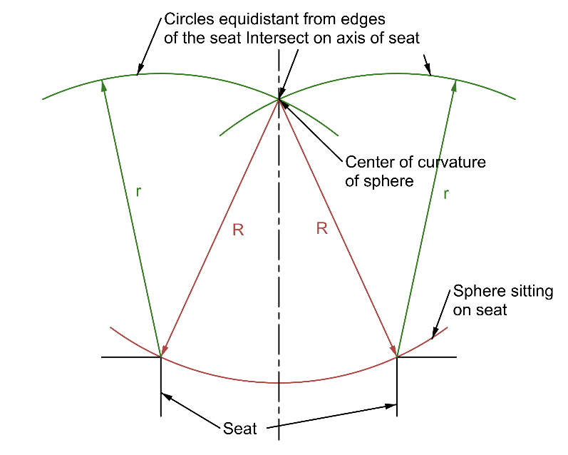
Fig. 2 Center of curvature of sphere on seat lies on the axis of the seat
Of course, tilting the lens element in Fig. 1 by tapping will move the center of curvature of R2. To center R2 you must decenter the seat. The procedure to center the lens and seat is the same basic procedure as aligning an alignment telescope to an axis as discussed at the end of Chapter 3. In this case, the axis of the rotary table is our reference axis. We look at the apparent center of curvature of R1 since it is farthest from the point of rotation of the lens in the seat and tilt the lens by tapping on its edge until the reflected image is stationary as the table rotates. The image does not have to be centered on the crosshair in the viewing instrument, it just must be stationary as the table rotates to assure the image is on the axis of the table.
Then you move the viewing instrument on the vertical slide to the center of curvature of R2 and decenter the seat until the reflected image is stationary. Again, the image need not be centered, just stationary. This adjustment will invariably throw the center of curvature of R1 off the table axis. These steps are repeated iteratively by tilting the lens when focused at the center of R1 and decentering the seat when focused at the center of R2 to bring the two centers of curvature onto the table axis. The centering is finished when each of the two centers of curvature remain stationary as the table rotates.
Each adjustment will bring the centers closer until the centering meets some specification for the tilt and decenter of the lens where the element in Fig. 1 is an analogue of a lens. A skilled operator centering much the same lens element will quickly learn that you generally want to undershoot, or depanding on the lens shape, overshoot, the adjustment to bring the lens to complete centration more quickly. You must also keep track of the azimuth of the rotary table so you don’t undo the previous adjustment by tapping on the wrong side of the lens. Centration to bring the optical axis of the lens coincident with the axis of the rotary table is tedious but is as precise as the bearing of the rotary table and the patience of the operator. This is why this method of centering using a rotary table has been used for over a century. In a subsequent Chapter we will talk about an easier way to do centering without the need of a rotary table.
A decided short cut in the method is to know the seat is well centered to the rotary table axis in the first place as is obvious from Fig. 2. Then the only adjustment to the lens is tilting by tapping on the edge while looking at the optical center of curvature of R1. Effectively, having the seat centered orthogonalizes the centering process in that the decentering is completed and only tilting is necessary to finish the job. This idea is the reverse of the bond ring method mentioned in Chapter 6. There the lens was cemented in the bond ring free of tilt so only decenter was left to correct.
It is still wise to check that the center of R2 is still centered before assuming the job is done until you have enough experience to be sure there is no need to check. The least burr or contamination on the seat will ruin the assumption that the seat is acting as if it were centered.
To recap the points of centering an optical axis of a lens element to a rotary table axis we need:
- A fixed focus optical sensor capable of projecting a crosshair or point source of light and detecting the return image of the projected source
- The sensor must be mounted on a vertical stage and centered above the axis of a rotary table
- The two centers of curvature of the lens element must be accessible to the sensor by moving the sensor along the vertical stage and/or by changing the objective lens of the sensor
- There must be means of adjusting the lens in both decenter and tilt
- When the reflected images of both centers of curvature are stationary (within some acceptable tolerance) in the sensor as the table is rotated, the optical axis of the element is coaxial with the axis of the rotary table
- If the lens in incapable of being both tilted and decentered, or only one center of curvature is accessible, it is impossible to fully center the lens unless the seat accepting a spherical surface of the lens is well centered to the axis of the rotary table and the center of curvature that is opposite the one sitting on the seat
Before finishing this Chapter I should say that we have been discussing centering a lens optically on a rotary table. Mechanical centering is possible and is often used particularly for larger diameter lenses. Reviewing this method will reinforce what has been said about optical alignment.
To center a lens on a rotary table the seat is first centered on the table using mechanical indicators to assure the seat runs true to the table as in Fig. 3.
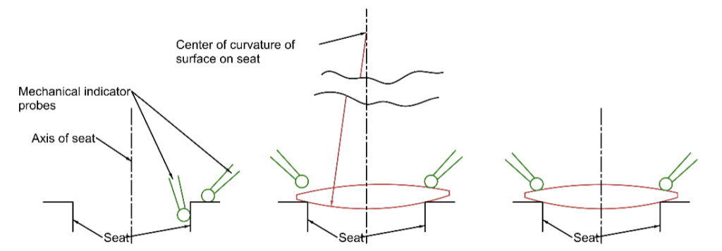
Fig. 3 Mechanical center of a lens on a rotary table
On the left of Fig. 3 mechanical indicators are used to assure the seat is running concentric and perpendicular to the axis of the rotary table. When the lens is first set on the seat it is clearly tilted and decentered, so the indicator shows a tilt or wedge in the lens as the table rotates. However, the center of curvature of the surface on the seat lies on the axis of the rotary table. As the lens is centered it rotates about the center of curvature until the indicator on the edge of the lens shows no height variation as the table and lens rotate. Then the center of curvature of the upper lens surface also lies on the axis of the table. Note the tip of the indicator remains the same height from the seat as the table rotates.
This also illustrates how bell cup centering machines work where lenses are made, see Fig. 4. The surfaces of the lens are squeezed between well centered cups to force the axis of the lens onto the axis of the cups. Obviously, this technique works best for steep bi-convex lenses and least well for meniscus lenses. The good news is that centering is most critical for lenses with considerable power and less so for weak lenses. The same holds true for centering in general but these are cases where the centering between pairs of weak lenses is critical because the wavefronts between the lenses have substantial spherical aberration.
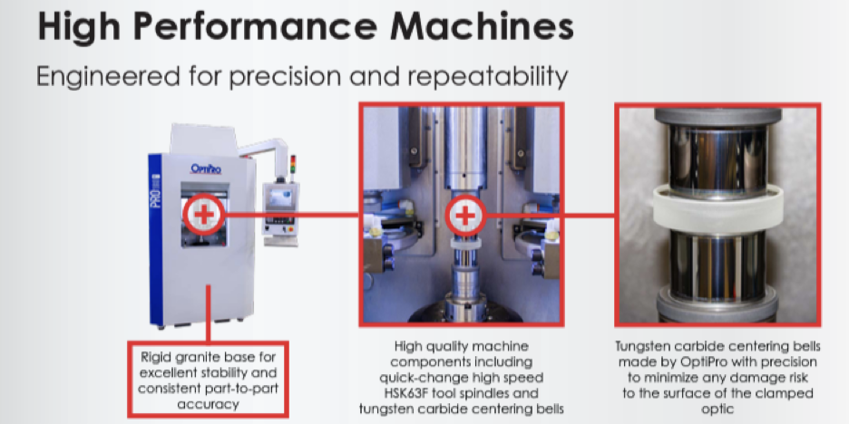
Fig. 4 A screen shot from OptiPro’s website of bell centering cups seen squeezing a lens in the right hand photo
(I am not trying to play favorites here. Many optical machine manufacturers make similar machines. This company just had a picture that perfectly illustrates the point I was making.)