There is no better way to describe an autostigmatic microscope (ASM) than to call it an autocollimator (AC) with a microscope objective attached to the front. This converts the AC from an instrument that measures 2 angular degrees of freedom (DOF) into an instrument that measures the location of the center of curvature of a spherical surface or wavefront in 3 DOF.
To illustrate this definition there is no better than the original description in the English literature, an article by a Mr. C. V. Drysdale in the Trans. Oct. Soc. London, 1900 called On a simple direct method of determining the curvatures of small lenses. In his introduction, Drysdale says he was surprised there was no instrument capable of measuring the radii of lens surface so “I immediately set to work to devise such a method, … capable of measuring the curvature of any spherical or cylindrical surfaces, from quite shallow curves to those of less than a millimeter radius.”
Drysdale’s Fig. 2 showed the method as reproduced here with my notes to the Figure.
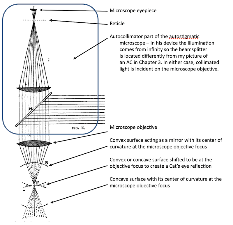
Although Drysdale’s original purpose was to measure radii of lens surfaces by first focusing at the center of curvature and then on the surface and measuring how far the microscope moved between the two measurements, he did not stop there. He went on to show his autostigmatic microscope could view aberrations in lenses by what we would now call the “Star test”, as well as measure object/image distances, focal lengths and principal plane locations. Suggested it could be used to measure index of refraction of glass and be used as a focimeter to aid optometrists.
Modern ASMs have essentially the same optical layout as Drysdale’s and can do all he described and much more thanks to modern light sources and digital detectors. I will continue this discussion using the Point Source Microscope (PSM)* as the example of an ASM because I am most familiar with it and use it on an almost daily basis in my lab. The optical path in the PSM is shown in Fig. 1 when used as an ASM.
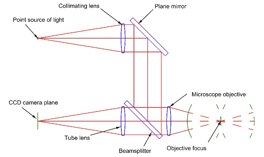
Fig. 1 The optical path in the Point Source Microscope when used as an ASM
While the optical paths are the same as in Drysdale’s paper, the light source is the free space end of a single mode optical fiber pigtailed to a laser diode at 640 nm to produce the smallest practical, but very bright, point source producing a near perfect spherical wavefront at the objective focus. In place of the eyepiece and user eye there is a digital camera with a 3.45 µm pixel, megapixel image in the ASM focal plane displayed on a monitor for convenient viewing and saving in a 16 bit format for post processing. At times we forget how much the laser and modern computer have changed optics. Most of the reasons the PSM can do more than Drysdale’s ASM is the vast range of controlled intensity of the source and the sensitivity range of the digital camera.
The PSM is also an autocollimator when the microscope objective is removed because of the collimated beam path inside as shown in the Fig. 2. Because the PSM has a shorter collimator, or tube lens, than most commercially available ACs, it has an angular sensitivity 3-4 times less but a larger angular field of view. This less angular sensitivity is a trade against the instrument size and mass.
Although Drysdale does not mention it, his ASM had a feature that the PSM also has, it can be used as an ordinary reflection inspection microscope as in Fig. 3. There is a second light source in the PSM to give full field, nearly uniform illumination over a ~1 mm object space field of view (FOV) with a 10x microscope objective. This gives the option of locating a particular feature on a sample within the 1 mm FOV and illuminating a very small patch with an intense spot of light via the laser diode, or an external source fiber coupled into the PSM. Figure 4 gives an example of piece of paper with printed lines and the small bright image of the Cat’s eye reflection.
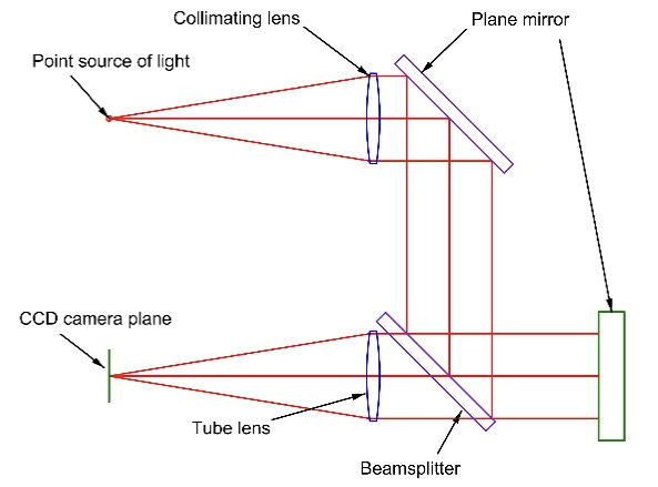
Fig. 2 PSM as an autocollimator
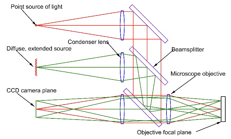
Fig. 3 PSM as an inspection microscope using diffuse illumination, and using the point source illumination
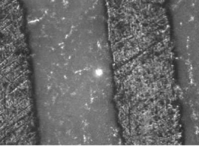
Fig. 4 Image of a 1 mm square area of a sample with a bright Cat’s eye reflection
Now that I have described an ASM and how it works I will discuss a few of the mechanical hardware tools used with the ASM and with autocollimators.
As mentioned earlier, an ASM locates a point in 3 degrees of translational freedom, but a point is an abstract idea. A solid, spherical ball is a physical realization of a point whose location is determined mechanically by touching its surface at 4 or more points to calculate its center. Because an ASM also finds the center of the ball to the same or better precision than it is found mechanically, the ball serves as an artifact that transfers an optical datum to a mechanical one, or vice versa.
Steel balls are a perfect type of ball for this purpose. They are commodity items available in standard sizes and qualities. Half inch, 7/8” and 1.5” balls are particularly useful because these are the sizes of spherically mounted retroreflectors (SMR) and their mounts, or nests, used with laser trackers. Fig. 5 shows a 0.5” ball and nest while Fig. 6 shows a 0.5” SMR with a corner reflector mounted so its vertex is at the ball center. Because SMRs are mounted in spheres, an ASM is useful to locate them within a few µm of their required location.
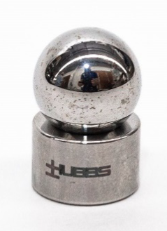
Fig. 5 ½” steel ball and nest designed to place the ball center ½” above the base
Fig. 6 ½” Spherically Mounter Retroreflector. The cube corner apex is at the ball center
Pin or plug gauges are similar commodity items for use with an ASM, see Fig. 7. When the ASM is focused on the axis of the cylindrical gauge the reflection is a line image located in 2 translational and one angular DOFs. If the gauge is measured at 2 points along its axis, an ASM establishes the axis against which the plug gauge rests. Later is this series when we talk about alignment of asphere we show how plug gauges are useful datums for locating sagittal and tangential radii of curvature.
Obviously plane mirrors are useful with autocollimators. Aids in tilting plane mirrors are precision rotary tables and goniometers, sine plates and angular gauge blocks. See Figs. 8 and 9. Sine plates and angle gauge blocks are relatively inexpensive methods of controlling angles to about 1 second of arc. Because you can use an angle gauge block in 2 directions, it only takes 9 gauge blocks to duplicate any angle between 0 and 90 degrees to 1 second of arc. Compound sine plates create 2 orthogonal angles by inserting standard gauge blocks between the platform and roll.
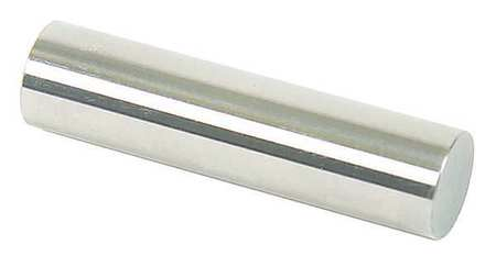
Fig. 7 Plug gauge
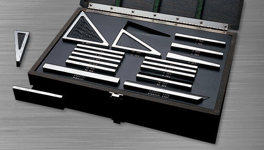
Fig. 8 Set of angle gauge blocks
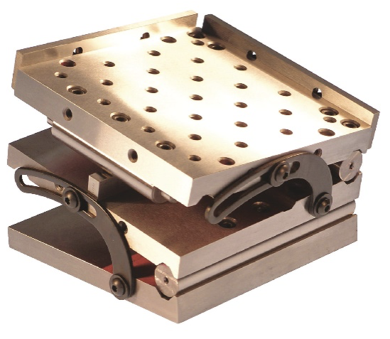
Fig. 9 Compound sine plate
To make an angle of 5°, for example, with a 10” sine plate you use a 0.872” gauge block because sin(5) = 0.08715.
Now that we have covered most of the hardware used to perform optical alignment we will move on to the definition of an optical axis and how to locate it for single elements as well as lens assemblies in the next Chapter.
*Full disclosure, my company, Optical Perspectives Group, LLC makes and sells the PSM.