In the Introduction to this series of articles on optical alignment, I said there were three basic methods of alignment. This article presents my thoughts on these methods. My approach may be a bit unconventional, but I hope this way of beginning makes the whole idea of alignment easier to understand. To illustrate the three approaches, I will consider the case of a concave mirror as an initial example.
(After reviewing this note it is clear I have not discussed the tools used for alignment such as autocollimators and alignment telescopes. I will do that in the next article, so you know the details of each instrument and have some idea of its sensitivity and range of measurement before I discuss each of the 3 methods of alignment in detail.)
The three methods are 1) exact alignment, 2) alignment by aberration and 3) alignment with a Bessel beam. The exact alignment method should be familiar to everyone and is most easily illustrated by means of a concave, spherical mirror. The center of curvature of a spherical mirror, or surface, is found by focusing an alignment telescope (AT), an interferometer (INT) or an autostigmatic microscope (ASM) at the center of curvature as in Fig. 1. When the reflected light is centered on the cross hair of the AT or ASM, or there are no tilt fringes in the (INT), the focus of the test instrument is at the center of curvature, a point, in 3 translational degrees of freedom (DOF).
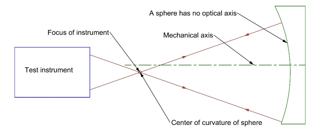
Fig. 1 Alignment instrument at center of curvature of a sphere, a point defined by 3 DOF
The second method, alignment using aberrations, is best illustrated by thinking of aligning a concave, parabolic mirror autocollimated with a plane mirror as in Fig. 2. Here the test instrument is at the focus of the parabola looking at the reflected image in a double pass test arrangement. Unless the plane mirror is tilted precisely perpendicular to the optical axis of the parabola, the reflected image will not be centered on the crosshair or tilt free interferometer. The plane mirror is first tilted in 2 degrees of freedom (DOF) to center the reflected light on the test instrument. Unless you are extremely lucky, the centered image will be comatic or aberrated. You use the coma to adjust the tilt of the plane mirror while keeping the image focused on the crosshair while reducing the coma as much as possible to achieve alignment.
The dashed lines in Fig. 2 show that when the focus of the reflected light does not return coincident with the focus of the outgoing light, the rays are not normally incident on the plane mirror. This amounts to retrace error, a term from interferometry, where the reflected rays follow a different path than the incident ones. This is why the return spot of light must be kept centered while reducing aberrations.
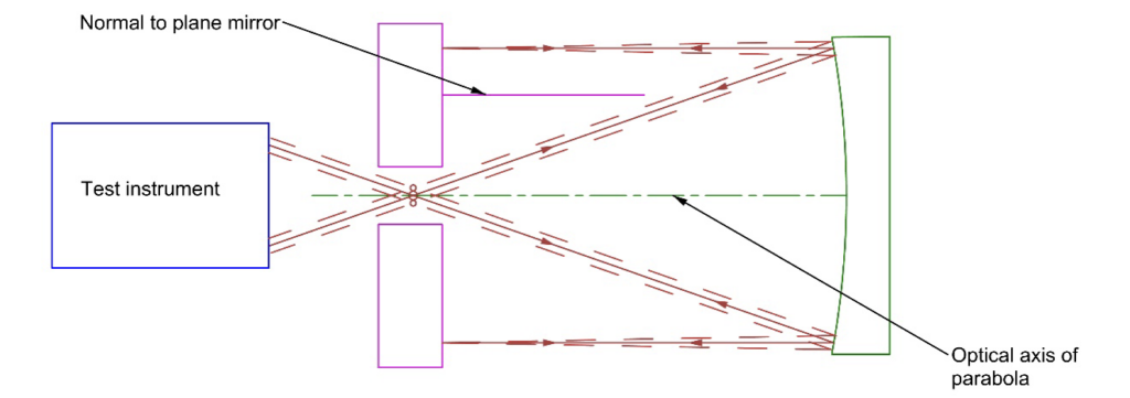
Fig. 2 Alignment of a parabola using aberrations. The outgoing rays must be coincident with reflected rays and the normal to the plane mirror parallel to the axis of the parabola to eliminate aberrations
These two methods are simultaneously similar but different. I call the first method exact because depending on the sensitivity of the test instrument, you can locate the center of curvature to less than 1 um, and often better assuming you have a good test environment. This is about as exact as you can get, and the degree of precision is largely independent of the f/# or cone of light the mirror subtends. On the other hand, you have only located the mirror in 3 translational degrees of freedom, because a sphere is a point in space if its radius is reduced to zero, and a point is defined by only 3 translational DOF. The corollary to this is that a sphere, or spherical mirror, has no optical axis. It does have a mechanical axis defined by its periphery, but no optical axis because it is still a sphere no matter how it is rotated about its center of curvature.
The parabola, however, does have an optical axis given to it by the slight departure from a pure spherical shape by its being a parabola. The same goes for any asphere. When the reflected light comes back to the test instrument centered, all this guarantees is that the light collimated by the parabola is incident on the flat mirror normally. It does not mean the flat is perpendicular to the optical axis of the parabola. This takes two more DOF to satisfy this condition and if the condition is not satisfied, you have coma. It then becomes a matter of how sensitive you are to the coma, the aberration, with your test instrument to determine how well you can align the parabola. This sensitivity governs which test instrument you must use to achieve the desired degree of alignment.
(Sidebar – A further consequence of the difference between a sphere and an asphere is that a spherical wavefront remains spherical independent of how far it propagates because all lines from its center of curvature intersect the sphere at normal incidence. This is not the case for an aspheric wavefront. It changes shape as it propagates. To see why to first order, consider an off axis ray from the center of curvature of a parabola, or any asphere. From similar triangles the ratio of y/R is constant as the ray propagates. The difference between a sphere and asphere is proportional to y^4/R^3 and this ratio is not constant.)
You may ask why can’t I use the center of curvature and the focus of the parabola to use the exact method to do the alignment? In theory, you can, as some textbooks show. However, in practice it is difficult to simultaneously view both the center of curvature and focus. This is why aberrations are generally used in this alignment situation. In turns out there are many similar situations where it is easy to draw pictures of optical tests, but it is difficult to impossible in practice to get to the required centers of curvature to do exact alignment. Then you are forced to use aberrations.
However, alignment with aberrations is a bit tricky because at the beginning of alignment the aberrations will be large and it is not always obvious whether your adjustments are making the aberrations worse or better. This is why you will want to stop down the aperture of the system to reduce the aberrations to the point where you can make sense of them and see that you are going in the right direction to reduce the aberrations. Just as when using a microscope to examine a specimen, you start with the lowest magnification objective to locate the feature of interest and then switch to higher and higher power objectives using the turret.
(Sidebar – The first time you attempt to align some optical component always presents you with the worst possible alignment situation. You have no idea how sensitive any part of the setup is to being in the correct location before the next is added. It is not obvious which adjustment to make first, or even which way to turn the adjustment to make the alignment better. It is very frustrating, particularly if you are working alone and there is no one to ask for advice. There are also times when it is best to work alone; too many cooks… This is why I am excited about the third method of alignment. It is pretty easy to see what you are doing because you have direct feedback.)
The third method of alignment uses a Bessel beam. This is a new method under development because we have recently shown a Bessel beam propagates through an optical system as though it was a single paraxial ray [1]. With a paraxial ray, if you know the ray height as it comes from infinity and enters the first surface, first order optics tells you the height and angle the ray will exit the lens. The plane within the lens where the two paraxial rays intersect, the principal plane, tells us where the lens is along the optical axis of the system (1 DOF) and the equation of the optical axis of the lens determines the remaining 4 DOF. Since simple optical systems have rotational symmetry, the Bessel beam is all that is needed to locate the lens in 5 DOF. We will have more to say about this new method of alignment as we proceed.
In the next couple articles, I will discuss each of the three methods of alignment in more detail to give a better idea where one or the other is more useful depending on other considerations, for example, what equipment you have on hand. Speaking of equipment, I will discuss typical instruments used for optical alignment.
REFERENCES:
[1] Parks, R. and Kim, D., “Physical ray tracing with Bessel beams”, Proc. Winter Topical Meeting, Precision Optical Metrology Workshop, pp. 72-6, ASPE (2023)