After finishing Chapter 1, I was going to jump right into discussing using the PSM for optical
alignment. As I started an outline for this Chapter, one of the entries was locating the center of
curvature, and this led to radius of curvature which made me think that it would be best to
explain the origin of the idea of radius of curvature measurement first. Radius measurement
was what led me to find the C. V. Drysdale paper of 1900 titled “On a simple direct method of
determining the curvatures of small lenses” which is the first description of an autostigmatic
microscope in the English literature [1]. Ever since finding this paper I assumed there must be a
German paper pre-dating this
In researching for this Chapter I was surprised, although I shouldn’t have been, to find the basic
idea was first suggested by Foucault of the knife edge test, which is used at the centers of
curvatures of concave mirrors to test for the surface profile, or figure. The idea was further
expanded upon by his colleague, Dr. Adolphe-Alexandre Martin, a professor of chemistry and
physics in Paris, who is best known for discovering tintype photographic method for turning a
negative into a positive.
In 1877, Martin wrote a paper titled “Memoir on the methods used for determining the curvatures of
objectives, accompanied by tables suitable for shortening the calculation” [2]. He took Foucault’s idea
one step farther by describing what is meant by autocollimation and showed how it could be
used to test a singlet lens for homogeneity. In a further extension of the idea, he showed how to
use the test on a doublet to determine wavefront quality by having the doublet collimate the
light so it would autocollimate after reflection from a plane mirror.
As with the knife edge test, however, the point of light illuminating the mirror or lens must be
slightly separated laterally from the return image to avoid the source obscuring the image. It
appears that it was Drysdale that introduced a beamsplitter to allow the superposition of the
point of light illuminating the object under test with the return image, thus eliminating any
wavefront errors due to observing the object off axis. I will continue to look for other
references, but for the moment it looks like Drysdale gets credit for the idea of the original
autostigmatic microscope as a stand-alone instrument.
If you put a point source of light at the center of curvature of a concave sphere the rays are
normally incident and they reflect on themselves to the original point source as in Fig. 1a. You
might ask, why not put a beamsplitter between the point source and mirror, but any plane
parallel plate in a diverging beam introduces both astigmatism and coma. The beamsplitter
must be in collimated space to avoid introducing aberrations
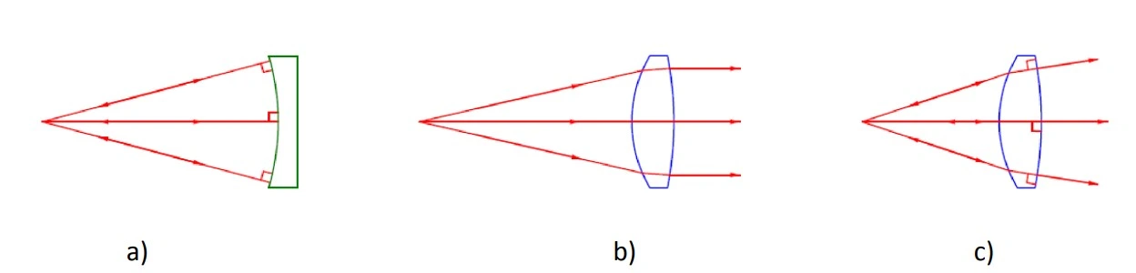
Fig. 1 Reflection of a point source of light at the center of curvature of a spherical mirror, a),
collimation of a point source at the focus of a lens, b), and autocollimation of a point source at
the optical center of curvature of the second surface of a lens, c).
What Martin describes in the test of a single lens is what I have called the optical center of
curvature of the second surface of a lens, the autocollimated return image of a point source of
light after refraction at the first surface of the lens, then the reflection at the second surface and
finally, de-collimation by the first surface back to a well-focused spot. In his explanation of
autocollimation, he says to first imagine the point source is at the focus of a positive lens, so the
rays come out collimated, as in Fig. 1b. Then move the source toward the lens so that the rays
leaving the lens start to diverge. If the source is moved even closer to the lens there comes a
point where the rays diverge enough so they are normal to the second surface, as in Fig 1c. This
point is the axial location of the optical center of curvature, and the distance to the second
surface represents the optical radius of curvature of the surface. Here the rays from the second
surface reflect along the same paths to their origin. This is how he describes “autocollimation”
because the first surface of the lens both collimates the light initially, and then de-collimates the
light on its return from the second surface.
The idea of autocollimation is expanded by his second example where the whole doublet does
the collimation and de-collimation of the beam reflecting off a plane mirror. In general, the term
autocollimation refers to any optical test where a defined source of illumination, or illuminated
target, reflects on itself. Another way of expressing the idea is to call it a double pass test since
the light passes through all the optics going to and reflecting from the final surface, generally
the object under test. The errors measured this way are twice those when the optics are used
single pass, as they would be in the case of observing with a telescope or microscope.
Radius measurement
With this introduction to the idea of autocollimation, we can proceed to the measurement of
radius on curvature. If we set up a test as in Fig. 1a with a point source at the center of
curvature of mirror, the radius is just the distance between the point source and the surface of
the mirror. This is typically measured with a tape measure for longer radius mirrors, or an inside
micrometer for mirrors about 30 to 300 mm. You can see why this measurement is difficult to
make precisely when the radius is less than the length of an inside micrometer. Even at 300 mm,
when you place an inside micrometer between the mirror and the point source, you want to
avoid touching the point source, often the end of a fiber, or damaging the mirror yet getting as
close as possible. This can easily lead to an error of 0.5 mm or more. That means the relative
error in the measurement is on the order of 0.5/300 = 0.17%, not exactly precision when it
comes to optical measurements.
This is where an autostigmatic microscope (ASM) is useful. In fact, the first lengthy description
of an ASM in English since the Drysdale paper is from a paper by W. H. Steel who was then
employed by CSIRO, the Australian standards laboratory, about measuring the radii of contact
lenses [3]. It is from this 1983 paper that I found the reference to Drysdale, but at this time
most microscopes still used finite conjugate objectives which meant that the beamsplitter in the
microscope introduced a small amount of aberration. Drysdale’s implementation of the ASM,
however, uses collimated light. In the French literature, Albert Arnulf wrote his doctoral
dissertation in 1930 about the measurement of radii and discussed ASMs. [4]
The reason the ASM is useful for short radii is that you do not need to measure between the
point source and the mirror surface, you just measure the distance you move the ASM from the
center of curvature to the mirror surface as shown in Fig. 2 for a relatively long radius sphere.
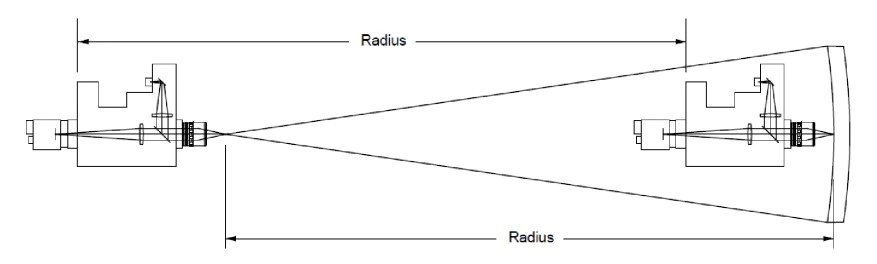
Fig. 2 Measurement of the radius of curvature with a Point Source Microscope
On the left, the PSM is at the center of curvature of the spherical surface and on the right, it
was moved to focus on the surface. The radius of curvature of the surface is the distance the
PSM was moved. It is important that the measurement be made in a straight line from the
center of curvature to the surface so that when the PSM focuses on the surface it is on a normal
to the surface. If you start the measurement at the surface, you will often be laterally displaced
from the center of curvature when you have moved the center of curvature of the surface.
Taking our previous example of a 300 mm radius surface, with the PSM and a 10x objective you
can find both the center of curvature, the confocal position, and the focus at the surface, the
Cat’s eye reflection, to a few µm in most cases. If we assume a total measurement error of 5 µm
then the relative error is .005/300 = 0.002% provided the mechanical scale is precise to the µm
level. In both cases, the practical limit of the precision of the measurement is more mechanical
than optical.
Short and long radius measurement
The PSM is particularly useful for the measurement of short radii for the reasons we have
explained. The next question is how short a radius can you measure? With a 10 x objective, you
can measure the radius of a 0.1 mm ball to about ±6 µm, maybe a little better. Now, however,
the relative measurement error is more like 6/50 ~ 12%. There is no reason not to use a 100x
objective, but you still have about a 1% relative error. For very short radii, an interferometric
measurement is the best choice for a precision result. Ultimately the precision will be limited by
how well you can measure the distance the ball, or lens, was moved from confocal to Cat’s eye.
For long radii, and here I am talking about several meters, a tape measure works well if the test
is vertical, so gravity keeps the tape straight, but this is not satisfactory if the path is horizontal
as it often is. Here a laser distance measuring device is handy such as shown in Fig. 3.
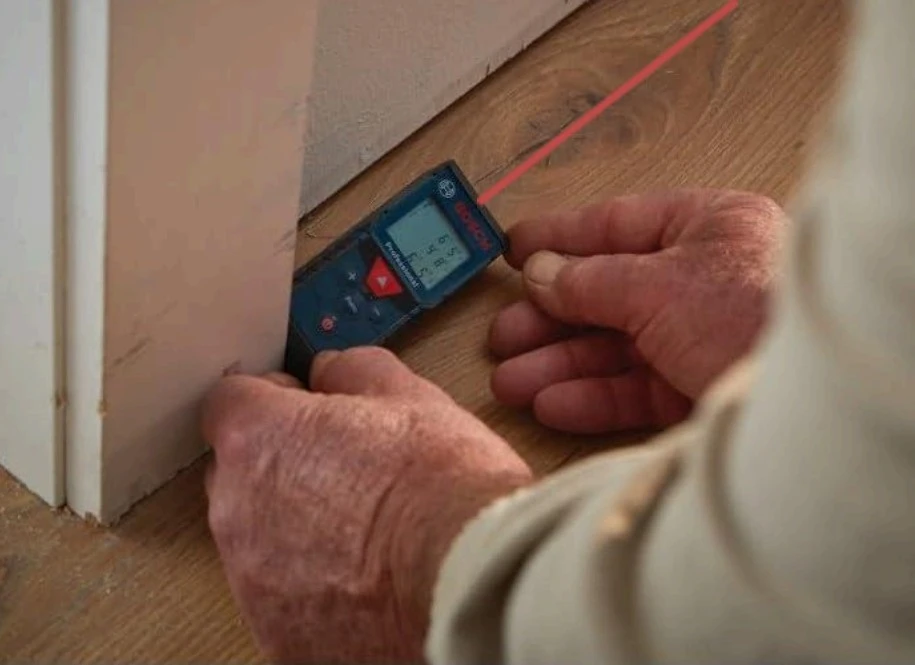
Fig. 3 Laser distance measuring tool backed up to a door jamb. The laser beam comes out on
the opposite side, or top of the tool, where it scatters off the wall it is pointed at.
Once you have the PSM at the center of curvature you bring the rear side of the laser tool up to
the PSM focus and get a Cat’s eye reflection from the backside of the tool while the laser is
pointed at the mirror. Then click the measure button. Since the tool is calibrated to measure
from its rear surface as illustrated in Fig. 3, the reading from the tool gives the mirror radius
directly to on the order of 1 mm. Even for a vertical path, this is probably the preferred method.
Conclusion
In this note we have reviewed the principal use of autostigmatic microscopes, the measurement
of radius of curvature. Something that is seldom noted because it is related to the craft of
optical polishing as opposed to metrology is that almost every optical shop has an ASM for
measuring the radii of test plates that are in turn used to measure the radii and irregularity of
polished lens surfaces. In this age of interferometers, the use of test plates is a dying art.
Martin appears to have coined and defined the term autocollimation in 1877, while the term
stigmatic refers to the use of a point source of light in the microscope. In addition, Martin
explained the idea of an optical center of curvature of a lens surface, something I have called
the optical center of curvature. The first practical form of an ASM seems to have been described
in English by Drysdale in 1900. The practical necessity of using an ASM for the precise
measurement of short radii was also shown until this use was largely supplanted by
interferometers.
In the next Chapter we will talk about how to measure the radius of curvature where it is
difficult to get to the center of curvature of the surface of interest, and other methods of
measuring long radii.
References
1 Drysdale, C. V. “On a simple direct method of determining the curvatures of small
lenses.” Transactions of the Optical Society 2, no. 1 (1900): 1-12, iopscience.iop.org
2 Martin, Adolphe. “Memoir on the methods used for determining the curvatures of objectives,
accompanied by tables suitable for shortening the calculation.” In Annales scientifiques de l’École
Normale Supérieure , vol. 6, pp. 3-61. 1877.
3 Steel, W. H. “The Autostigmatic Microscope”, Optics and Lasers in Engineering 4 (1983)
217—227.