ABSTRACT
The Point Source Microscope (PSM) utilizes infinite conjugate optics internally. When the microscope objective is removed, the PSM is an autocollimator. Unlike conventional autocollimators, which use a reticle pattern for illumination, the PSM employs a single-mode fiber. The PSM camera captures a well-focused, circular return reflection when a perfect plane mirror is aligned perpendicular to the autocollimator’s axis. However, if the mirror has residual power, the return image appears slightly out of focus. Irregularities in the mirror produce a correspondingly irregular image. The point source illumination makes the autocollimator sensitive to grating patterns and cylindrical optics, things classical autocollimators cannot sense.
Keywords: Optical alignment, optical axis, Point Source Microscope, autocollimator, parallelism, angle metrology
1. INTRODUCTION
The Point Source Microscope (PSM) was originally developed about 25 years ago as an optical alignment tool, primarily for locating centers of curvature and focal points in optical systems. Following current microscope design principles, the PSM employs infinite conjugate optics internally. This type of microscope configuration automatically makes the PSM into an autocollimator when the microscope objective is removed.
Over the years, we occasionally used the PSM as an autocollimator—not because it was designed for that purpose, but simply because it was available and convenient. While our documentation has acknowledged its utility as an autocollimator, we never truly regarded it as such. To us, it has always been a precision alignment tool. For alignment purposes, an x-y-z stage is sufficient to position the PSM’s focus at a desired point in space—providing the three degrees of freedom needed for most alignment tasks.
One reason we did not emphasize its use as an autocollimator is that use as an autocollimation requires a tip/tilt mount to align the PSM’s optical axis with the test surface. Unfortunately, the PSM’s footprint does not lend itself easily to a commercially available tilting mount, and we had not designed a suitable one.
After years of considering this limitation, we were finally compelled to design a tip/tilt mount—not for autocollimation per se, but to mount PSM on a coordinate measuring machine (CMM), one of our preferred platforms for optical alignment. The CMM serves as a large, precision x-y-z stage, allowing sub-micron placement of the PSM focus over a large volume of space. Knowing the 3D location of centers of curvature and foci from the system’s optical and mechanical design, the user can simply bring the PSM focus to the correct location, adjust the optic until its center of curvature aligns with the PSM focus in all three degrees of freedom, and fix the optic in place with UV cement or other means. The customer who bought the first PSM we made used the PSM this way on a CMM for the assembly of an optical system. This use on a CMM cut assembly time drastically and improved the performance of the optical system.
With a tip/tilt mount now available, I revisited the idea of using the PSM as a dedicated autocollimator. I already knew it was well-suited for small optics—a student had asked me to help her measure the wedge in a 2 mm diamond window heat sink. The measurement was straightforward.
In this article, I’ll introduce the relevant PSM hardware and optics, discuss software considerations, and then present a series of practical examples using test components from our lab. I’ll conclude by highlighting applications that are especially well-suited—or even unique—to the PSM in autocollimation mode.
2. TOOLS FOR ALIGNMENT
2.1 Hardware tools
Figure 1 shows the optical path of the Point Source Microscope (PSM) configured as an autocollimator, that is, used without its objective lens. Illumination is provided by the free-space end of a single-mode fiber pigtailed to a 635 nm laser diode. The resulting ~0.1 NA Gaussian beam is collimated and directed out of the PSM via a beamsplitter through an 8 mm diameter aperture. Reflected light from the surface under test re-enters the PSM and is focused onto a 1/2.9″ format CMOS camera with 3.45 µm pixels by a 100 mm effective focal length tube lens.
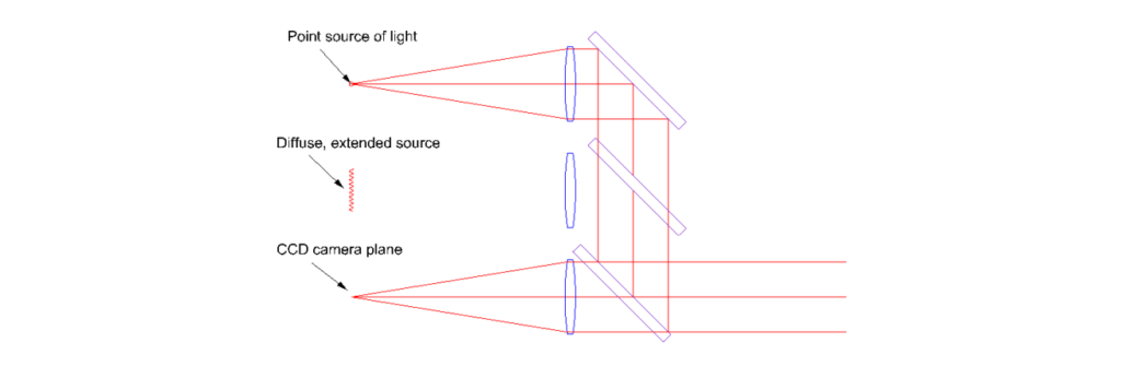
Fig. 1 Optical path in the PSM when used as an autocollimator
A 1-pixel shift in the centroid of the reflected spot corresponds to an angular deviation of .00345/100 = 34.5 µrad (7.12 arcseconds). The PSM software fits a 2D Gaussian to the return spot using the camera’s full dynamic range (10 to 12 bits), enabling centroiding sensitivity of ~0.1 pixels—equivalent to approximately 0.7 arcseconds. The full angular capture range along the longer dimension of the camera is ±1.42 degrees.
Historically, the two main technological advances that make the PSM viable as an autocollimator are its compact, high-brightness laser source and its digital camera. Before the advent of laser diodes, optical alignment instruments relied on incandescent bulbs or xenon arcs. Xenon arc lamps could create small pinhole sources but were relatively dim. Incandescent bulbs allowed reticle illumination, but are unsuitable for pinhole illumination, which is why traditional autocollimators were built around illuminated reticles rather than true point sources.
The primary challenge in using a traditional autocollimator is not the angular measurement itself but acquiring the reflected beam during the initial setup. A significant amount of time is spent simply aligning the autocollimator to see a reflected beam. In contrast, the PSM’s laser diode provides enough intensity to follow the outgoing and return beam using a white card, even with room lights on. For uncoated or low-reflectance surfaces like bare glass, dimming the ambient light may help—but even then, beam visibility and setup remain quick and straightforward.
Before electronic cameras became commonplace, the only way to observe the return spot was through an eyepiece, which introduced two major limitations. First, the autocollimator had to be positioned where the user could physically access the eyepiece—often in awkward or impractical positions. Second, the human eye is far less sensitive than modern CMOS cameras. The PSM overcomes both problems by using a highly sensitive digital camera to display the return spot on a conveniently placed monitor, improving both ergonomics and sensitivity.
The final advantage of the hardware design is the PSM’s compact size, about as big as a hand and its small mass, less than a kilogram. Its small footprint allows it to be mounted on commercial lab x-y-z positioning stages and used in tight spaces where traditional autocollimators would be too bulky and massive. Together, these advantages make the PSM a much more flexible and user-friendly autocollimator for both lab and field applications.
2.2 Software tools
The PSM was originally developed as an alignment tool optimized for measuring position, not angle. As such, the software is designed to report lateral displacements in microns, using a calibrated scaling factor. The calibration factor is changed by the user whenever a different magnification objective is used. This scaling gives direct readout of lateral shifts between the return spot and the electronic crosshair in microns in object space.
When the PSM is used as an autocollimator, the scaling factor is determined solely by the pixel pitch of the camera and the focal length of the tube lens, nominally 100 mm. For the current configuration the camera has 3.45 µm pixels so the calibration factor is set to 3.45 um/pixel for angle measurement. For example, if the reflected light returns 100 µradians from the PSM optical center the light is incident 10 µm from the detector crosshair, or 10 µm/3.45 µm/pixel = 2.90 pixels from the crosshair. With the calibration factor set to 3.45 um/pixel, the distance reported by the software is just 2.90*3.45 = 10 µm. Thus, to convert the distance measurement to angle you multiply the µm reading by 10 to get µradians, or by 2.058 to get arc seconds.
It is important to note that the PSM software measures the angle of the reflected light, not the angle of the test surface. For a plane mirror, the surface tilt angle is half the angle measured by the PSM due to the law of reflection. If the camera is replaced or its pixel pitch changes, the scaling factor must be updated accordingly to maintain accurate angular measurements. For angle measurements the calibration factor is always the camera pixel pitch.
3. TRADITIONAL AUTOCOLLIMATOR APPLICATIONS
3.1 Small optics
We begin with a classic application of an autocollimator: setting the angle of a plane mirror. In Figure 2, the mirror was adjusted so that the return spot from its surface appeared slightly above and to the left of the PSM’s electronic crosshair. To demonstrate the PSM’s performance with small apertures, we then placed a 3 mm aperture over the mirror, producing the image on the right. The only noticeable change was a slight increase in spot size, consistent with diffraction effects introduced by the reduced aperture, but the centroiding is not compromised.
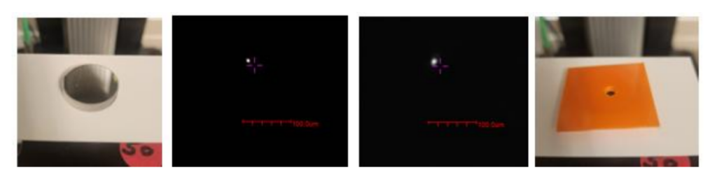
Fig. 2 Plane mirror and its reflected spot (left) and reflected spot from same mirror stopped to 3 mm. (The spot image pictures were cropped to 140 pixels from the full frame of 1440 pixels in width)
As previously mentioned, the PSM can work with very small optics. We have successfully used it to measure optical components as small as 2 mm in diameter, making it well suited for precision alignment tasks involving miniature optics because all the collimated light exiting the PSM is in the 8 mm aperture, not a 30 mm or more aperture of a classical autocollimator.
3.2 Measuring the wedge in a window
Here the PSM is viewing a BK7 window with a nominal 30 minute wedge. The reflected spots from the two surfaces of the wedged window are shown in Fig. 3. They are separated by 761 pixels or 26255 µradians = 2nα. Using the index of BK7 as 1.515 at 640 nm we find α = .008665 µradians or 0.4965°, essentially the nominal 30 minutes wedge. (A second measurement against an autocollimating flat lets you calculate the index of the glass.)
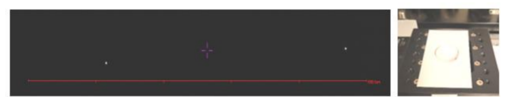
Fig. 3 Cropped monitor picture of the two reflected spots from with side of a wedged window
3.3 Measuring the error in a hollow retro-reflecting prism
A hollow, one-dimensional retroreflector was examined next to yield the results in Fig. 4. The distance between spots was 9 pixels or 311 µradians, double the error in the retro. The true retro error is about 0.5 arc minutes.
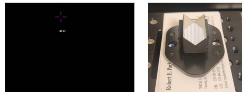
Fig. 4 Measuring the angular error in a hollow retro-reflecting prism.(In all the monitor pictures the spacing between the inside tips of the magenta cross is 31 µm and 87 µm outside.)
3.4 Measuring the error in a cube beamsplitter
This beamsplitter cube demonstrates a measurement that can be challenging to perform with a conventional autocollimator. In a classical autocollimator, wavefronts that are nearly parallel produce overlapping reticle patterns making it difficult to resolve small angular differences. In this case, the PSM clearly resolves two distinct spots that are approximately 2.5 pixels apart—equivalent to about 9 arcseconds. While I didn’t pause to identify the contributing surfaces, it’s likely that the upper prism was well fabricated and contributed the 9 arcsecond deviation. A third spot, located approximately 2.6 arcminutes from the pair, is consistent with expected tolerances for the angular deviation in transmission from a catalog-grade, cemented cube beamsplitter.
Some may question the use of business cards as a background for the cube, but they serve a practical purpose. The cards demonstrate that a white background behind the cube has no effect on the measurement. The return spots from the AR-coated surfaces of the beamsplitter appear crisp and well-defined against the completely black monitor background. The PSM’s autogain function is used to prevent pixel saturation, ensuring high contrast and accurate spot detection.
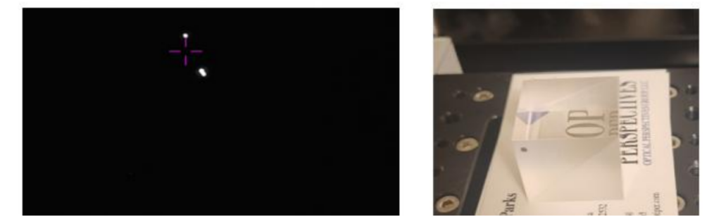
Fig. 5 Measurement of the angular error in a beam splitter cube in both paths simultaneously

Fig. 6 Measurement of the angular error in a different cube with a cemented window. A reflection from the cemented interface is also visible in the enhanced image
4. APPLICATIONS NOT POSSIBLE WITH TRADITIONAL AUTOCOLLIMATORS
4.1 Viewing of an aberrated plane wavefront
Because the PSM uses a point source for illumination the reflected image is a well-focused, point such as that in Fig. 1. However, if the surface under test as in Fig. 7 (right), or wavefront is not perfectly plane, the image will show the aberration as this plane mirror does when squeezed with a furniture clamp.
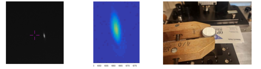
Fig. 7 Reflection from a stressed plane mirror (left) with a Matlab image and pixel scale for a detailed viewing (center)
4.2 Measurement of linear grating spacings
The PSM AC is useful for measuring coarse grating spacings over the range of about 1 lp/mm to 80 lp/mm, the lower bound limited by the 8 mm aperture of the AC and the upper bound by the acceptance angle of the camera, about 3°. In Fig. 8 we are measuring the spacing of a 20 lp/mm grating that gives a spot spacing of 368 pixels, or an angle of .0127 radians. The 50 um per line pair also gives an angle of .635/50 = .0127 radians.
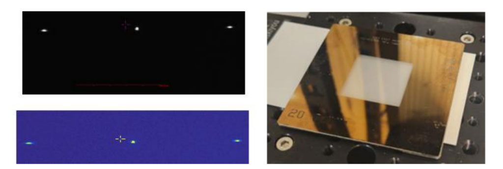
Fig. 8 A 20 lp/mm grating and the 0 and 1st order diffracted spots, the upper from the PSM monitor and the lower from a Matlab image that makes counting pixels easier.
This is an example of a measurement that would be difficult to impossible to make with a traditional AC. The next example shows why such measurements might be useful.
4.3 Measurement of a polka dot beamsplitter pattern
In the process of looking for examples to use in this paper I came across a “polka dot” beamsplitter that I bought from Thorlabs some time ago and then never used for anything but realized it would be a perfect example of what could be done with the PSM autocollimator. Fig. 9 shows the result of the measurement.
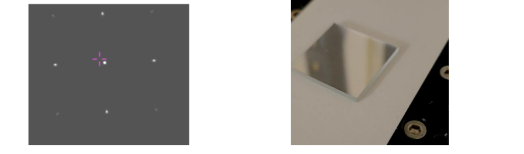
Fig. 9 Diffraction pattern from a “polka dot” beamsplitter with 122 pixel refracted light spot spacing
Once I took the picture of the diffracted spots it was obvious that a grating like this was perfect for doing 2 dimensional angular calibration of the AC. But it was a shock to find that the 122 pixel spot spacing gave me a diffraction angle of .242° which was way off from the catalog value that claimed the spacing of the “dots” was 56 um that gives an angle of .635/56 = .01134 = .650°. I doubled checked everything, but nothing made sense since I hadn’t changed the measurement setup since measuring the linear grating.
Because the PSM also works as a microscope, it was easy to go back and make microphotographs of the two patterns and the problem became obvious as seen in Fig. 10.
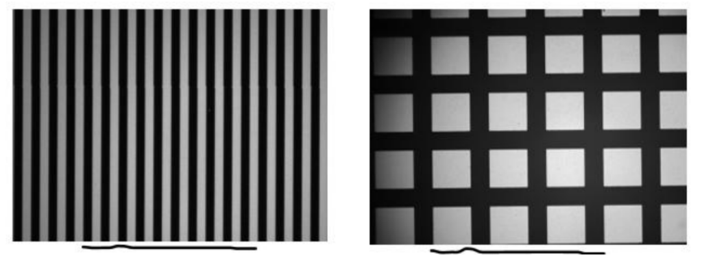
Fig. 10 The line under the linear grating pattern is 10 lines long and was copied under the polka dot pattern. It is clear the polka dot spacing is not 56 um, but more like 150 um
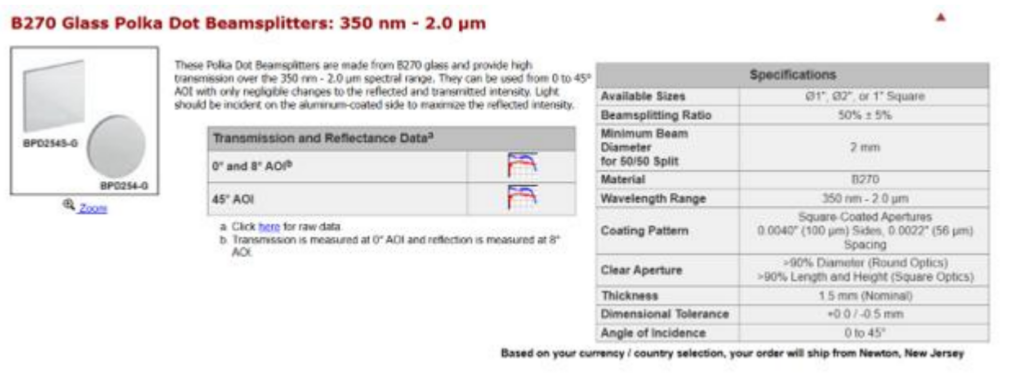
Fig. 11 Page from the Thorlabs on-line catalog about the Polka Dot beamsplitter with the spot spacing
The line spacing of the linear grating matches the diffraction angle expected based on the inscribed 20 cycles/mm on the grating pattern. The “polka dot” pattern is much more like 150 µm spacing that gives a diffraction angle of .635/150 = 4233 µrad = .2425°, almost exactly what was measured. This goes to show two things, you can’t believe everything in the catalog, and that it is useful to have a convenient method of checking every critical parameter in your test setup. (Measure twice, cut once!)
4.4 Reflection from a cylinder lens
As I was going through optics I could use for demonstrations of the PSM as an AC I came across a cylinder lens. While I knew the PSM as an autostigmatic microscope could easily pick up the axis of a precision pin or cylinder lens I had a hunch I could get a return from the autocollimator. As in Fig 12, yes, you get a return.
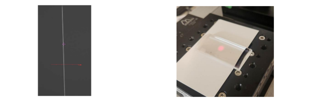
Fig. 12 Reflection from a cylinder lens that determines two axes of rotation
If the lens is tilted about either axis perpendicular to the axis of the cylinder, the reflected line will either rotate in the plane of the monitor or move left/right. If the microscope objective is replaced in the PSM, the line image when the PSM is focused on the axis locates the axis in two translations perpendicular to the cylinder axis. In one setup you can measure all four degrees of freedom of the axis of the of the cylinder.
5. DISCUSSION
When used in traditional applications, the PSM compares favorably with classical autocollimators in both angular sensitivity and dynamic range. While it does not match the sensitivity of high-end electronic autocollimators, a software enhancement—AI4Wave [1]—can be applied to achieve comparable angular resolution through advanced image processing.
One of the key advantages of the PSM in autocollimator mode is its use of a true point source for illumination. This allows it to perform tasks that are difficult or impractical for conventional autocollimators. Most notably, the PSM can directly visualize aberrations in a reflected plane wavefront. This capability enables quality assessment of optics designed to produce or reflect plane wavefronts, such as flats or collimating elements.
The point source illumination also improves the visibility of closely spaced reflections. When two return beams are nearly overlapping, the PSM makes it easier to resolve and distinguish them—something that is often challenging with extended-source autocollimators.
Additional applications include imaging diffraction orders from coarse one- and two-dimensional gratings. This can be used to evaluate grating pitch, regularity, and fabrication quality. Conversely, a grating with a well-known pitch can serve as an angular reference artifact, allowing precise calibration of the PSM’s angular scale.
Finally, one of the most versatile capabilities arises when the PSM is used in both its autostigmatic mode (with an objective) and autocollimating mode (without the objective) within the same setup. This dual-mode functionality allows simultaneous measurement of both the position and tilt of cylindrical optics, such as a cylindrical lens, or precision pin, a single, compact test configuration.
6. CONCLUSIONS
The PSM is inherently well suited for use as an autocollimator—because it already functions as one. Its unique point source illumination not only enables sensitivity to angular deviations but also allows detection of aberrations in plane wavefronts and low spatial frequency structures, such as one- and two-dimensional grating patterns. Additionally, its small aperture makes it particularly effective for measuring the angles of small optical elements.
In more traditional autocollimator applications, the PSM offers practical advantages due to its compact footprint and low mass, making it ideal for test setups with limited space. Furthermore, since the PSM uses a digital camera rather than an eyepiece, it can be positioned in locations that would be awkward or inaccessible for classical autocollimators requiring direct visual access.
REFERENCES
[1] AI4Wave software, https://www.innovationsforesight.com/product-category/ai4wave/