ABSTRACT
Bessel beams have found use in the alignment of transmissive optics for some time. They are also used for the alignment of reflecting optics when used in the imaging mode, that is, when the wavefront is near spherical. However, there are cases where it would be useful to use the Bessel beam for alignment of far-off axis aspheres to order to get the asphere aligned close enough to its final position that light will go through the system in the imaging mode. In another mode, the Bessel beam is used to determine the normal to a free form surface.
1. INTRODUCTION
Bessel beams created with Axicon gratings are quite useful for aligning transmissive optics.[1,2] Using a Bessel beam allows one to align a single optic, or an optical system, in tilt and decenter without having to move the sensor such as an autostigmatic or autocollimating microscope between lens conjugates. This technique of establishing a reference axis in space means that it is no longer necessary to use a rotary table to create an axis. The steps to achieve alignment are straightforward left/right-up/down adjustments that make hand/eye coordination easy. This makes the process faster and less tedious for those doing the work which, in turn, leads to greater productivity.[3] The advantages of using Axicon gratings associated with transmissive optics encouraged me see if the same basic ideas could be applied to reflecting optics.
The paper is organized to first review a few basics associated with the alignment of transmissive optics for background. Then I show that a Bessel beam projector can be used along with an autostigmatic microscope (ASM) to align reflective optics without any new hardware because the Bessel beam is so relatively unaffected by the aberrations you would expect in the case of spherical wavefronts. There are limits, however, to this technique when the Bessel beam begins to turn into an array or pattern of dots of reflected light. There is useful alignment information in this pattern of dots, but it is easier for me to build new hardware than develop new theory for analyzing these patterns.
Then I describe a set of optics that serve as a Bessel beam projector and detector of the reflected beam. Since there is no such device that I am aware of, I will call the instrument an autostigmatic Bessel Beam projector (ABBP) since it is “auto” in the sense of projecting a target and sensing the reflected target. To be useful the ABBP is aligned so that it is clear the reflected Bessel beam passes through the same point as the projected beam. We describe the method of doing this alignment.
Finally, we show some initial results of reflecting the Bessel beam off plane and spherical mirrors. Obviously we could look at a plane mirror with a collimator, but it is reassuring to see a reflection that behaves as expected. A little more surprising is to see an autostigmatic reflection from a spherical mirror at a location in space other than its center of curvature. The distance from mirror to ABBP is immaterial. This is followed by looking at the ABBP reflections from two diamond turned off-axis parabolas.
Because this work is recent, we have not had time to test in practice some of the many things the ABBP could be used for, but we will outline several areas of potential usefulness including non-contact surface shape measurement and the alignment of reflecting optics when it is impossible or inconvenient to get to their centers of curvature.
2. BACKGROUND ABOUT AXICON GRATINGS AND BESSEL BEAMS
Axicon gratings are a chrome on glass pattern of concentric, evenly spaced circles, in this particular case, 50 line pair per mm of pattern radius. This gives a diffraction angle of about ±1.819° when illuminated with collimated 635 nm light. In our case it is easier and more broadly useful to illuminate the grating with a point source from the end of a single mode fiber. With the point source a couple hundred mm from the grating, the -1st order diffracts towards the center of the grating pattern close to the grating and the angle gradually opens until the beam leaves the grating normal to it and then diverges. This means we have a useful Bessel beam tens of meters in length.
Fig. 1 illustrates the beams the point source creates with its spherical wavefront. The transmitted Bessel beam core is a continuation of the line between the point source and grating pattern center.
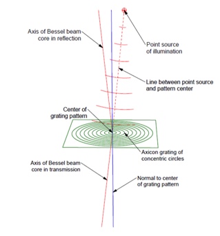
Fig. 1 The reflected and transmitted Bessel beam cores created by the spherical wavefront from the point source illuminating the Axicon grating and diffracting
The reflected beam core is mirrored about the normal to the pattern center. Obviously, when the point source is on the grating normal to the pattern center, the reflected core passes through the point source. This also means that a point source below the grating but on the grating normal will produce a transmitted core coincident with the normal. We have previously shown how a combination of a point source behind the grating and the point source in an ASM are used to align a single element or an entire optical system to an axis in both tilt and decenter.[4]
2. BESSEL BEAMS AND REFLECTING OPTICS
It is obvious that a point source of light at the center of curvature of a spherical mirror will reflect back upon itself, and that this property is used to align mirrors, and to measure their radius of curvature when a Cat’s eye image is also obtained from the mirror surface. Trying to find a reflected image anywhere other than these two conjugates from a spherical mirror is impossible. However, using a Bessel beam, the seeming impossible is quite possible.
To make this statement plausible, consider a plane mirror. We will get a reflection looking at the mirror with a collimator. If we use a Bessel beam, we should expect to get a reflection back if the mirror were parallel to the grating producing the Bessel beam and if we could illuminate and view the mirror at normal incidence. If the plane mirror were tilted and we get a reflection, then for the untilted case we would have to believe that would also be the case.
Fig. 2 shows an example where the plane mirror is tilted 30° and we use an Axicon grating with 50 lp/mm illuminated by a point source 270.4 mm from the grating. After the beam travels 744.5 mm, rays from a grating annulus with a radius of 6.25 mm form the core of the Bessel beam in the focal plane. While a specific distance was chosen for the Figure, the Bessel beam exists anywhere along the normal to the grating and beyond the focal plane in the picture, each distance along the normal due to diffraction at a different radius of the grating. 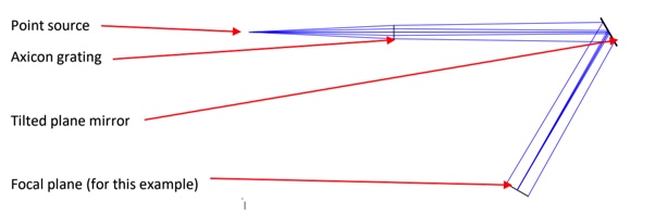
Fig. 2 Reflection of a Bessel beam off of a plane mirror tilted 30°
Taking this same example of reflection from a tilted mirror but adding power gives us the situation in Fig. 3 where the tilt angle is -1.5°, about as close as we can get without blocking the Axicon beam projector with the PSM objective. This situation where we cannot get closer to the projected beam is exactly the reason for needing the ABBP described below. For reference, this 500 mm radius of curvature mirror would produce about 1.3 waves P-V of astigmatism when illuminated by a point source displaced 1.5° from its center of curvature.
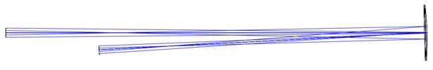
Fig. 3 Bessel beam incident on a tilted, 500 mm radius of curvature concave mirror.
The Axicon grating at the left is illuminated by a point source 232 mm to the left of the grating. The PSM objective focal plane is 350 mm from the mirror to give a feel for the scale of the drawing.
We set up an Axicon grating and PSM closely approximating the ray diagram in Fig. 3. This is shown in Fig. 4 (where the tilt angle of the mirror is about 5° rather than the minimum possible of 1.5°) along with a picture of the Axicon beam and a Zemax spot diagram covering the field of view of the PSM objective. Fig. 4 is intended to be an overview of how the measurements were made so the results are easier to explain as the tilt of the mirror is increased from 1.5° to 8.5°. The Figure is also meant to show that the distance from the Axicon grating to the mirror was much less than the 500 mm radius of curvature and the distance from mirror to PSM objective even less. If a point source of light was placed where the Axicon grating is there would be no image to see anywhere in the plane of the PSM objective.
Using the setup in Fig. 4, the tilt of the spherical mirror was increased in 1° steps to 8.5° and the PSM moved so the Bessel beam was approximately centered on the detector. Fig. 5 shows a sequence of Bessel beam images along with Zemax spot diagrams corresponding to each image. Since you can make the spot diagram in Zemax look like almost anything you want using a Bessel beam source, images are meant only to indicate a trend and it is immediately apparent the ray diagrams look nothing like the images themselves, but both show a trend as the tilt angle increases.
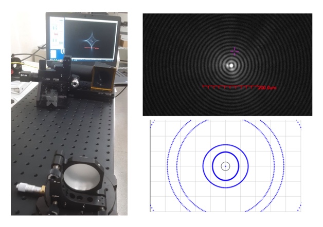
Fig. 4 (Left) experimental set up with Axicon grating (square) in right middle with PSM objective facing the spherical mirror in the foreground and image of the Axicon beam on the computer monitor for the pictured mirror tilt of about 5 degrees. (Upper right) Bessel beam spot for a 1.5° mirror tilt (note scale bar) and (below) Zemax geometrical optics spot diagram over approximately the PSM field of view of about 1 mm.
As seen in Fig. 4, (upper right) the Bessel beam image at 1.5° tilt of the spherical mirror is an almost perfect, unaberrated image. By the time the spherical mirror is rotated to 2.5° (see Fig. 5), the image is no longer what we expect as an unaberrated Bessel beam image. The bright core is gone and it now has a cross shape. The Zemax ray spot diagrams reflect a similar behavior in quantity if not quality. By that I mean the spot diagram for 1.5° is almost perfectly round, while the 2.5° spot shows clear ellipticity with the rings nearly touching each other. By the time the tilt is 3.5° the spot diagram rings of rays intersect one another.
I believe what is happening is that rays from adjacent zones of the Axicon ring pattern are interfering with each other. With the plane mirror, the ray angles relative to one another in the pupil are not changed on reflection while with the spherical mirror the ray angles change with radial position in the pupil so that as they propagate they intersect. The particular diamond shaped pattern here is almost certainly due to the almost pure astigmatism one gets as a spherical mirror is used off-axis.
There may be work that talks about this in the literature but I have not come across any although I did not search extensively. To be sure there is useful of information in these diffraction patterns about wavefront error, and certainly the aberrated images are still useful for alignment purposes.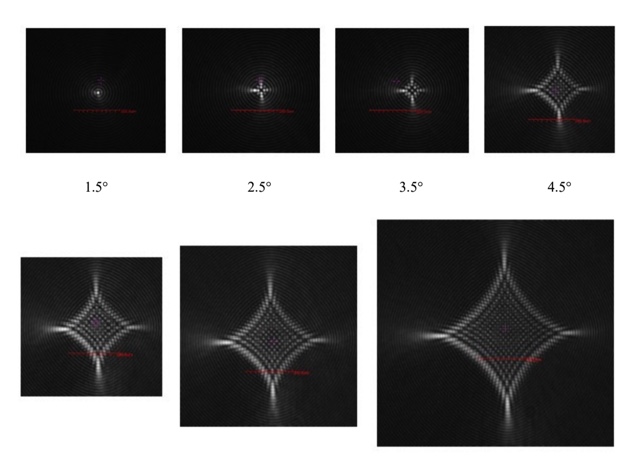
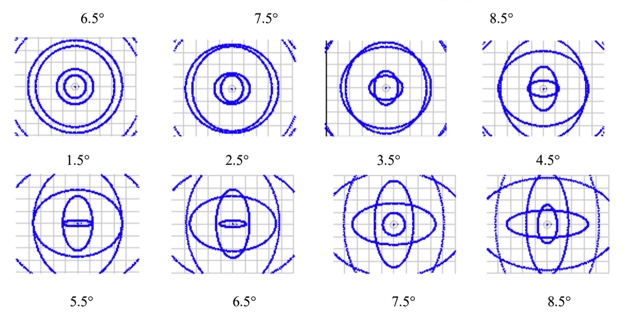
Fig. 5 Bessel beam images as the 500 mm radius mirror was tilted from 1.5° to 8.5° (top). The image at 5.5° was overlooked by mistake. Zemax geometrical ray diagrams scaled to a 1 mm image plane, about the same as the image plane of the 10x objective used to capture the real images (lower)
For the moment we will leave this topic of non-normal Bessel beam reflection. I believe it has usefulness for alignment in situations where a center of curvature or other lens conjugate is inaccessible, but the approach is nowhere as useful as a Bessel beam projector where the outgoing and reflected beam share a common axis.
3. AXICON BESSEL BEAM PROJECTOR/DETECTOR
Just as for most optical tests, it would be useful to have a Bessel beam alignment device where the Bessel beam was incident on the surface at normal incidence, the same as you would use an interferometer, for example. A way of doing this is shown in Fig. 6.
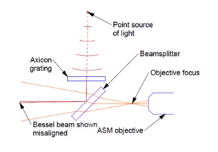
Fig. 6 Axicon grating Bessel beam projector/detector (ABBP)
The point source behind the Axicon grating, the Axicon grating and the beamsplitter are the main elements of the Axicon Bessel beam projector/detector (ABBP). The device connects directly to the objective of a Point Source Microscope. The distance between the objective focus and the beamsplitter is not critical but should be a small as possible for the most useful ABBP. The point source must be aligned so the reflected light returns through the objective focus. The alignment process is discussed below.
Because we know a point source creates a Bessel beam when illuminating an Axicon grating, a question might be, why use a beamsplitter, why not just put the grating out in front of the objective? The answer is that the Axicon grating throws away most of the light incident on it. With little light passing thorough the grating once there is too little to detect coming back through a second time. This is why the beamsplitter is introduced after the grating. It would certainly make a more compact and convenient device if the Axicon grating could be used in double pass, but it is not practical.
3.1 Alignment of the Bessel beam projector/detector
In Fig. 6, the point source behind the grating is shown producing a spherical wavefront that is incident on the Axicon grating and producing a Bessel beam in transmission that is shown misaligned. This makes it clear why the point source must be aligned. Also, there is a spherical wavefront emanating from the ASM objective focus. If the reflected Bessel beam is to appear aligned with the ASM, the beam must pass through the objective focus. A way of assuring this is to place a spherical mirror to the left of the beamsplitter whose center of curvature is centered on the ASM objective focus. Using this condition, any ray emitted from the objective focus will strike the spherical mirror surface at normal incidence and reflect back coincident with the outgoing ray at the objective focus.
In Fig. 7a, we show a spherical mirror whose center of curvature is centered on the objective focus and show how the reflected, misaligned ray misses passing through the objective focus. It is clear that when the point source, or the Axicon grating, is moved so the Bessel beam hits the spherical mirror at normal incidence, the beam will reflect back through the objective focus and appear aligned in the ASM as in Fig. 7b.
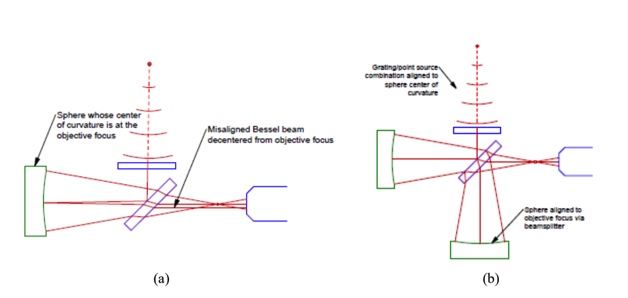
Fig. 7 Center of curvature of spherical mirror aligned to ASM objective focus using the ASM internal point source, and a misaligned ABBP (a). A well aligned ABBP where the Bessel beam is normal to the surface of either sphere whose centers of curvature are coincident with the objective focus (b)
Once the ABBP is aligned so that after reflection from the spherical mirror the Bessel beam passes through the objective focus, then a second spherical mirror whose center of curvature is also centered on the focus will also reflect the Bessel beam thorough the focus because the beam is likewise incident on the sphere at normal incidence. This procedure also shows the Bessel beam projector may be used either in reflection from the beamsplitter or in transmission. Depending on the experimental setup, one or the other configuration may turn out to be more convenient.
3.2 Bessel beam projector prototype
Before showing the use of the Bessel beam projector it is instructive to look at the hardware. This is not a finished design but merely hardware to demonstrate feasibility. Fig. 8 shows the Bessel beam projector/detector with the parts labelled so the hardware may be compared with the diagram in Fig. 7.
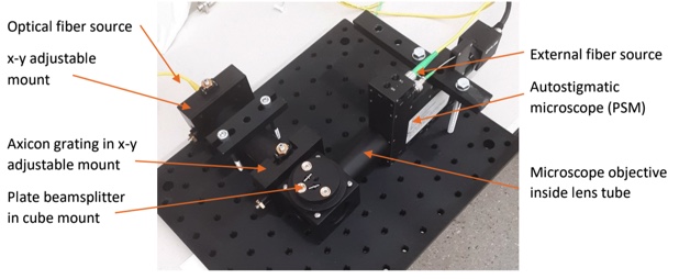
Fig. 8 A prototype Axicon Bessel beam projector/detector showing the direct connection to the PSM objective
3.3 Using the Bessel beam projector with a spherical mirror
Once the ABBP is aligned it was used to view a concave spherical mirror at various distances from the ABBP. At first one might say “So what?’. On the other hand, where else does one see a reflection from a spherical mirror other than the Cat’s eye focus at the surface or from the center of curvature? Fig. 9 shows the spherical mirror at several distances from the ASM and the reflected Bessel beam on the computer display.
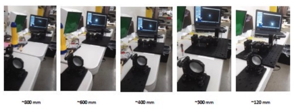
Fig. 9 A 500 mm radius spherical mirror at several distances from the ABBP.
The view shows the back of the mirror and the reflected, normal incidence Bessel beam on the monitor
No attempt was made to measure the distances precisely as this was just to demonstrate that one could get a reflected Bessel beam at various distances from the mirror. The core of the Bessel beam reflected at normal incidence is visible on the computer display in Fig. 9. Because it is difficult to see what is on the screen in the background of Fig. 9, Fig. 10 has enlarged, cropped screen shots of a couple of distances.
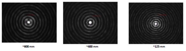
Fig. 10 Screen shots of the reflected Bessel beam from a 500 mm radius sphere at several distance from the Bessel beam projector. The red scale bar on each picture is 100 μm long.
The only difference in these pictures is that the ring diameters scale with distance because the sphere changes the convergence of the rays on reflection, and this is dependent on the diameter of the ring when it strikes the mirror.
3.4 Using the Bessel beam projector with an aspherical mirror
Next we used the ABBP to look at two diamond turned off axis parabolas at normal incidence, one a 15° OAP with an efl of 635 mm whose pupil was centered 167 mm off axis. The difference in sagittal and tangential radii was 33 mm giving a difference in sag over the aperture the Bessel beam covered of 2.7 mm of about 80 nm P-V. For all practical purposes this was a sphere over this aperture and the reflected Bessel beam in Fig. 11 (a) shows this. It is not obvious what the hint of a cross pattern in the image is due to. Regardless, this demonstrates a normal incidence Bessel beam reflection from a nearly spherical diamond turned surface with a stated roughness of <10 nm rms.
The other OAP was a 90° mirror with a parent efl of 25.4 mm and an aperture offset by 50.8 mm. Here the sagittal and tangential radii differ by 71.84 mm so at that over roughly 2.7 mm radius of the Bessel beam the P-V sag differed by about 25 μm, giving substantial astigmatism and some coma. It was not surprising then to see the breakup of the reflected Bessel beam in Fig. 11 (b) and (c).
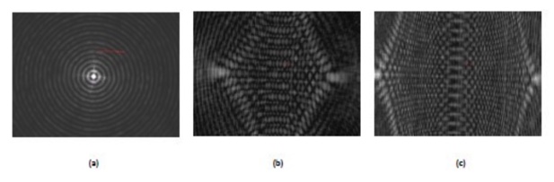
Fig. 11 Bessel beam reflections at normal incidence from a 15° diamond turned OAP (a), and from a 90° OAP toward the optical axis (b) and away from the optical axis (c). The pictures are not the same scale.
Figs. 11 (b) and (c) are of the same 90° OAP but 12 (c) is at the outer edge where 12 (b) is close to the optical axis. The pictures in this case are not the same scale. Fig 12 (a) is cropped but the 200 μm scale bar is visible and is close to the scale of the pictures Fig. 10. Fig 11 (b) is about 2/3rd of the full frame size while 11 (c) is full frame with a field of view of about 1 mm in the long direction typical of the 10x objective. These pictures have the 200 μm scale bar but it is all but invisible.
The dot patterns look indecipherable but probably contain as much information as an interferogram. Fortunately, for alignment purposes only a few point are needed. For example, it is obvious from Figs. 11 (b) and (c) that the azimuth of the OAP is tilted with respect to the camera azimuth. With further study it should be possible to learn more about the alignment of these kinds of surfaces using the Bessel beam projector.
4. USES OF THE BESSEL BEAM PROJECTOR
In addition to finding normals to reflective surfaces for alignment purposes, moving the Bessel beam projector across a surface provides slope information. The projector must be close enough to the surface under test that the reflected beam still lies within the objective field of view which for the case of a PSM with a 10x objective is ±0.5 mm.
4.1 Finding a normal to a surface
For a simple spherical surface there may be times it would be useful to know where the center of curvature was even though you could not reach the CoC because hardware was in the way. When the Bessel beam reflects back upon itself you know the beam was incident normal to the surface and therefore the CoC lies along that normal.
4.2 Finding the slope of a long radius asphere
In this case, if the asphere is moved through the Bessel beam and the projector/detector is close enough to the asphere that the reflected normal is always in the objective field of view, the slope is measured by noting the distance the reflected beam is from the crosshair and dividing this distance by the distance the objective focus is from the surface being measured. It is difficult to imagine the distance to the objective being less than 50 mm for a projector made of off the shelf components so the greatest slopes that can be measured are on the order of ±0.25°.
On the other hand, if the projector/detector were set up to rotate about the objective focus, and the rotation stage were driven by feedback from the detector when the reflected beam moved off the crosshair, the slope of the surface could be measured directly from the angle of the stage as the asphere was driven past the detector. This approach involves 2 moving stages, one of which is linear, a type of stage difficult to make precise. A better approach is below.
4.3 More general measuring of asphere slope
If the objective focus of the project/detector were at or near the center of curvature of the asphere and rotated about the focus of the objective, the detector would measure the slope departures from a sphere. This scheme has only one stage, a rotary one, and will work with any asphere for which the circle of least confusion is about 1 mm or smaller in diameter in reflection. As an example a 50 mm diameter, f/1 parabola would have a circle of least confusion of slightly more than 1 mm.
If the projector is rotated about its objective focus at the sagittal radius of curvature of the parabola, 103.135 mm, the reflected Bessel beam comes back as shown in Fig. 13.
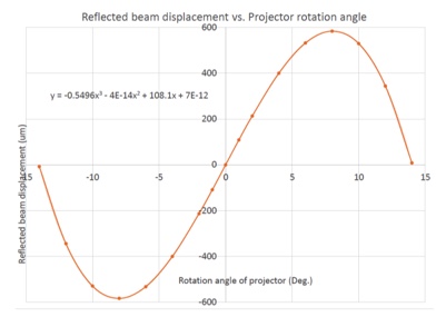
Fig. 12 Reflected Bessel beam displacement versus rotation angle when the ABBP objective focus is rotated about the sagittal radius of curvature of an f/1 parabola.
While this is not the usual method of measuring an asphere, the basic setup is a good match for a diamond turning machine with a rotary B axis, the axis needed to scan across the diameter of a newly turned surface. Scans across the diameter of the part are easily done with noting the displacement of the reflected beam as in the Fig., but as the total displacement is slightly over 1 mm, a two axis motion will do the job. In this case, as the projector is rotated, the X-axis of the diamond turning machine is driven to keep the reflected beam centered of the detector crosshair and the beam displacement read out directly as the X-axis motion versus rotation angle of the B axis.
The curve in Fig. 12 fits to a 3rd order polynomial nearly perfectly. If there is a 1 μm error in setting the cross feed when this f1 parabola is turned, the equation of the fit beam displacements changes by 1 unit in the 3rd decimal of the equation. This amounts to about a λ/4 P-V change in figure and would be largely noted as a change in radius, an error too small to notice in most situations. However, this does point out the sensitivity of the method.
Of course, one could also look for azimuthal errors with this same setup. With the projector aimed at a particular zonal radius, any errors as the spindle rotated with the work pieced mounted would show up as beam displacements in synchronism with the rotation.
One matter to be aware of is that the Bessel beam samples a finite size area of the work. For the particular Axicon grating described in this paper, the grating angle is about 1.8° so at a distance of 100 mm the sample area is about 3.2 mm in diameter. As long as this area has less than about 2 λ of astigmatism, the reflected beam will have a bright core. In this example, at the edge of the parabola there is about 1 λ of astigmatism. Even if there were more asphericity over the measured area, the Bessel beam breaks down gracefully, and will work for finding slope errors in rather steep aspheres.
Another answer to this problem is to decrease the diffraction angle by using a grating with coarser pattern of circles. It just happened that the spacing we originally chose, 20 μm/line pair was a good choice for a wide variety of situations. Like all things in optics, one size does not fit everything.
5. CONCLUSION
Picking up on the usefulness of Axicon gratings for the alignment of transmissive optics, we have investigated the use of these gratings with reflective optics. Because the detector of a Bessel beam, a PSM in this case, gets in the path of, or obscures, the Axicon grating or projector of the Bessel beam as one gets close to the normal of the reflecting surface, a useful implementation of an Axicon grating device for use with reflective optics must contain a beamsplitter. Further, because the Axicon grating makes inefficient use of the light incident on it, it is impractical to use the grating in double pass.
This forces a design where the focus of the PSM objective is behind the mechanical structure holding the beamsplitter and somewhat limits the flexibility over the use of Bessel beams with transmissive optics. However, there are still many useful applications of the Axicon grating Bessel beam projector/detector package. One obvious application is for on machine figure measurement of diamond turned optics.
The whole idea of using Bessel beams for the alignment of optics is so new that I am sure others will think of applications that are not obvious at this early stage.
REFERENCES
[1] Parks, R., “Alignment using Axicon plane gratings,” Proc. SPIE 10747, 1074703 (2018).
[2] Parks, R., “Design for alignment,” Proc. SPIE 11103, 1110302 (2019).
[3] Heinisch, J., Hahne, F. and Langehanenberg, P., “Rotation-free centration measurement for fast and flexible inspection of optical systems,” Proc. SPIE 11175, 111751B (2019).