ABSTRACT
Methods of centering without using a precision rotary table to establish a reference axis in space are several times faster than with a rotary table. However, finding an optimum method of establishing an alternative reference axis is challenging. We look at the small class of centering situations involving the precision cementing of doublets to illustrate the advantages of using a Bessel beam as the reference axis. Two approaches to centering illustrate the method; one involving first aligning the meniscus element and then adding the positive element, and the other, cementing the two elements and aligning the pair.
1. INTRODUCTION
We talk about the precision centering of lenses without the use of a rotary table because it has been shown to be much faster1 and less tedious. Cementing doublets is used as the example for two reasons; the alignment of the two lens elements has the necessary degrees of freedom in tilt and decenter to achieve perfect centering, and most color corrected lens systems use cemented doublets as the means of color correction. This means there are many lenses that need cementing so being able to speed up the process boosts productivity.
The paper is organized to first give a little background on the use of a Bessel beam as a reference axis rather than the rotation axis of a rotary table. Next we discuss the particular doublet used as an example and show where the conjugates are and discuss their usefulness to centering. Then we discuss the steps necessary to get a centering station ready for centering the lenses, and the setup of the hardware before doing the actual centering. Next are the two steps of centering, first to align the meniscus element to the vacuum chuck and then to align the positive element to the meniscus and show the precision of the method for a reasonably fast doublet pair.
A final section of the paper discusses some of the possible alternatives to the approach already described. The alternatives are sometimes required by the size of the lenses involved and some by preferences of the workers doing the cementing. The relative pros and cons of the methods are discussed to show why we made the choices we did with the particular hardware at hand. In some cases, these alternatives methods may be best but for most situations we feel the method first described has the overall advantage.
2. USE OF A BESSEL BEAM AS AN AXIS FOR PRECISION CENTERING
2.1 Why not use a rotary table?
Before describing a Bessel beam as a reference axis, we should mention the traditional method of precision centering lenses using the axis of a rotary table. If the table has a good bearing such as an air bearing, such tables are capable of creating an axis that is true to nanometers in terms of runout and sub seconds of arc wobble. If an item with rotational symmetry is placed on such a table it can be centered with respect to the table axis with equivalent precision by looking for deviations in motion synchronous with the table rotation. If there is no motion as the table rotates the item is “perfectly” centered about the table axis.
If rotary tables work so well, why look for another method of centering? One reason is the very thing that makes an air bearing table so good for centering, its freedom of rotation, comes back to be a disadvantage when trying to make an adjustment to what is on the table, the table wants to keep rotating as adjustments are made. The table can be grounded or clamped to stop the rotation but this invariably changes the centering or wobble slightly. Further, you have to keep track of the azimuth of the table. If it is 180° from where you think it is, a correction will lead to an error of twice what you were trying to correct. Finally, air bearing tables are expensive and require expensive infrastructure and maintenance. This is why a method of centering where nothing moves except the item being centered makes the centering process faster and less tedious.
2.2 Creation of Bessel beams
There are now several papers about how to create Bessel beams, or axes, from gratings of evenly spaced, concentric rings illuminated with a point source of light.2,3,4 These papers show that the Bessel beam axes are true axes even when the point source is several degrees off the normal to the grating pattern, and that an autostigmatic microscope is on the normal to the center of the pattern when the reflected Bessel beam comes back centered on the outgoing beam.
The particular grating used in our example has bright chrome on a glass substrate with rings spaced at 50 line pairs per mm. Illuminated with a 635 nm laser diode pigtailed to a single mode fiber, the grating has first order diffraction angles of ±1.819 degrees. The grating is about 70 mm below a window that sits on top of the base of the centering station. The window serves as a work platform, a part of the chamber of a vacuum chuck and it protects the grating. (A schematic diagram of the placement of the components is shown below in Fig. 3.)
2.3 Some properties of the Bessel beam
As shown in the previously cited papers, the Bessel beam created by the grating described above produces a central core with a FWHM of about 7 μm. The intensity of the core is about 12 times as bright as the first diffraction ring around the core. This means that the position of the core is easily found using a simple centroiding algorithm applied to all the pixels above a threshold set at about 50% the intensity of the core. A digital camera is ideal for this operation and can find the centroid to about 0.2 pixels by simply finding the center of gravity of the pixels above the threshold assuming 10 or more pixels above the threshold. It is noted that the diffraction rings around the core each have the same energy as the core so attempting to find the position of the core with a quad cell or continuous position sensitive detector does not work.
At any point along the Bessel beam, the bright core is produced by the cone of rays emanating from a particular chrome and bare glass ring on the grating. From the grating diffraction equation we have the diffracted angle as
where m is the diffraction order, λ the wavelength of the light and i the angle of incidence. In our particular case the point light source is about 215 mm from the grating. All the plus diffraction orders diverge and are not useful.
The angle of incidence to the innermost ring is .02/215 = 93 μradians, and to the outermost ring of the 50 mm diameter grating, 25/215 = .116279 radians. For the minus first order diffraction, the first ring of the grating diffracts to give sinα = ((-.635/20) + .000093) = -.031657. The tangent of this angle is -.0316729 so a ray starting at 20 μm from the center of the grating crosses the axis at .632 mm above the grating creating the beginning of the axis.
Moving radially toward the edge of the grating, the angle of incidence increases until it equals λ/d at a radial distance of .03175*214 = 6.79 mm. At this radial distance the diffracted ray exits normal to the grating, and for angles of incidence great than this, all the -1st order rays diverge. From this we see that the Bessel beam is useful for alignment purposes from <1 mm above the grating to infinity for our particular setup. It also shows that a smaller diameter grating, a finer spacing of the grating circles or a greater distance from point source to the grating would make more efficient use of the entire area of the present grating.
2.4 The effect of lenses on the properties of Bessel beams
Another aspect of the Bessel beam relates to its usefulness as a reference for centering. The beam can be thought of as a single ray in a lens design program because it is always visible, or accessible by an autostigmatic microscope, anywhere in the optical system so it can be followed surface to surface through an entire optical system. The beam does not depend on the conjugates of the system but is always visible to be tracked. Because it can be tracked at any distance along the optical axis of a system, not only can displacements be tracked but the angle of the beam as well.
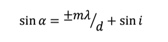
This is not to say that lenses inserted in the Bessel beam do nothing at all to the beam. While the core of the beam behaves as a ray, the pattern of core and rings is scaled according to the power of the elements through which the beam passes. For negative elements, the core and rings keep their circular symmetry but become larger while positive elements make the core and rings smaller. This property is illustrated by pictures of the Bessel beam during the centering of the doublet used in this paper as shown in Fig. 1.
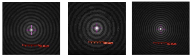
Fig. 1 Bessel beam with no element in the path (left), with the negative meniscus with an efl of -46.53 mm (center) and the cemented, positive doublet with an efl of 49.57 mm (right)
The three pictures in Fig. 1 are all the same scale as seen by the scale bar but the ring spacing and width are greater when the beam passes through the negative meniscus (efl = -46.53 mm), and the spacing closer and rings narrower when passing through the cemented, positive doublet (efl = 49.57 mm).
A final useful feature of the Bessel beam should be pointed out as in Fig. 2. When the Bessel beam core is out of the field of view of the autostigmatic microscope, the rings are still visible and the curvature of the rings indicate the direction to move the element to bring the core into the field of view. If the microscope were focused at a conjugate of a lens with no grating to create the Bessel beam, the display would be blank, or dark, until the core came into the field of view by chance of movement of the element. With the Bessel beam and the Auto Gain feature of the Point Source Microscope (PSM)5 used in these experiments, the rings from the Bessel beam are almost always visible to guide the core into the field of view. Fig. 2 does not do justice to the value of this feature because we also wanted to make it obvious in the picture where the core was at the upper left of the field is as well as show the rings. This picture also shows why a position sensitive detector is useless for finding the centroid of a Bessel beam, the energy is spread almost uniformly over a large area.
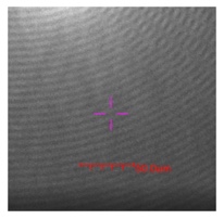
Fig. 2 Bessel beam rings with the core of the pattern outside the field of view of the microscope but to the upper left
3. DOUBLET USED AS AN EXAMPLE
3.1 The doublet design
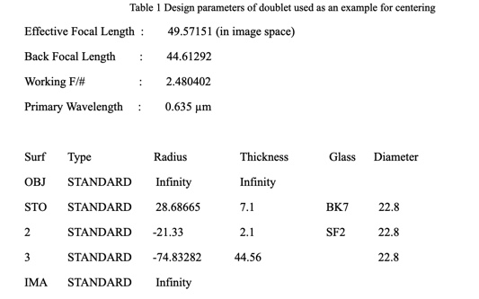
Now that we have reviewed the properties of the Bessel beam it pays to review the design of a typical cemented doublet, and the conjugates of the fairly fast doublet used in this particular example; see Table 1 for the design.
The lens, as used to image an infinite object, would have the positive element toward infinity to minimize spherical aberration, but for practical cementing purposes the lens is used with the elements reversed so the meniscus sits on a seat with the concave side up to capture the drop of cement as in Fig. 3.
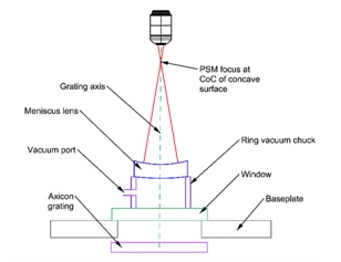
Fig. 3 The meniscus half of the doublet sitting on a vacuum chuck ready for cementing
3.2 Conjugates of the meniscus
With the meniscus sitting as in Fig. 3, there are 3 conjugates accessible to the PSM, the center of curvature of the concave side 21.33 mm above the surface as shown. The center of curvature of the convex side imaged through the concave is -131.765 mm below the concave side and the back focus is -46.531 mm below the concave side. The center of curvature of the concave side is easily accessible with any objective while the center of the convex side and bfl require objectives with working distances of at least 135 and 50 mm respectively. These conjugates can certainly be reached but require objectives with longer focal lengths to achieve the needed working distances and this requirement reduces the sensitivity of the objective to lateral motion. Working with the easily accessible center of curvature seems like the obvious choice in this case, and this example is typical of almost all doublets.
Since we have Fig. 3 to look at there is another aspect of the meniscus that does not depend on the design but is important to centering. As long as the grating is parallel to the window and the vacuum chuck is parallel, the center of curvature of the convex surface will lie on the axis of the seat of the chuck. If the chuck is centered on the Bessel beam then the center of curvature of the convex surface will lie on the Bessel beam. Conversely, if the chuck is decentered relative to the Bessel beam, the center of curvature of the convex side is decentered by the same amount independent of the how the lens sits on the seat.
3.3 Conjugates of the assembled doublet
Turning to the assembled doublet, there are again a number of conjugates available to probing as shown to scale in Fig. 4 so the conjugate distances are easily compared. The most obvious and most sensitive one because it is farthest from the lens is the back focus at 48.415 mm (different from the design because the lens is used reverse to the design) above the lens. Assuming the seat is centered, just looking at the back focus does not guarantee the lens is centered as cemented because a whole element rotation about the center of curvature of the convex surface of the meniscus by 1 minute of arc can be offset by a rotation about the cemented surface of 1.79 minutes. Also, having both transmitted and reflected Bessel beams are no help because both enter the convex side of the meniscus normal to the surface so they end up in the same place as the bfl, and are much less intense than the image from the bfl.
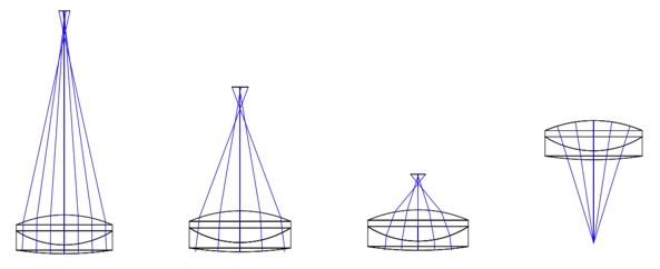
Fig. 4 The four conjugates of the assembled doublet as viewed with the PSM from above. Left most is the back focus, next reflection from the convex meniscus surface, the cemented surface and right most, reflection from the upper convex surface.
There will be a reflection from the convex surface of the meniscus 27.842 mm above the lens. As in the case of the bfl, since the Bessel beam intercepts this surface at normal incidence there is no evidence of a decenter between the cemented surfaces and the ratio of rotations is virtually the same as with the bfl. Also, the sensitivity to alignment is less because of the shorter distance above the cemented lens.
The reflection from the cemented surface at 8.067 mm above the lens is sensitive to the tilt of the cemented surfaces. If the meniscus is rotated 1 minute of arc in the seat, the positive element must be rotated 9.29 minutes to bring the reflected spot from the center of curvature so it is centered on the PSM crosshair. In this condition, the transmitted Bessel beam would be 83 μm decentered from the crosshair. Because the cemented interface is sensitive to misalignment of the cemented surfaces, reflection from this surface we will use for centering in both methods.
Lastly, we could look at the center of curvature of the convex last surface that lies 28.687 below the lens. Other than requiring a long working distance objective, this would look like an ideal conjugate in that the center of curvature of the meniscus is on the axis because of the seat and the center of curvature of the upper surface of the positive element is measured directly. In order to get the center of curvature on axis, the positive element must be rotated about the center of curvature of the cemented surface by 2.2 minutes of arc for every 1 minute of rotation of the meniscus. Unfortunately, the transmitted Bessel beam is shifted only 2 μm from the axis, a small shift for a rotation that leaves the center of curvature of the cemented surface 15 μm off the axis, or an angular error of about 2.3 minutes of arc. Thus it seems the surface that is most useful is the reflection from the cemented surface even though it is the closest to the lens. We will use this conjugate to compare with the behavior of centering as will be described in section 4.3 below.
4. SETTING UP FOR LENS CENTERING
Now that we have introduced the Bessel beam and the doublet used in this example, it is time to go through the steps required to setup a centering station for centering the elements in a doublet.
4.1 Setting the axis of the autostigmatic microscope
We use a Point Source Microscope (PSM) as the autostigmatic microscope to both illuminate the Axicon grating with a point source of light produced at the focus of the objective, but also to detect where the Bessel beam created by the Axicon grating reflects back onto the detector, a digital camera. The PSM is focused on a specular surface so the point source in the PSM creates a point spot of light on the surface. This point of light reflects back into the PSM to create a spot of light on the camera as shown in Fig. 5.
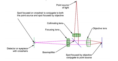
Fig. 5 An autostigmatic microscope focused on a specular surface to create a Cat’s eye image on the digital camera detector that is conjugate with the internal point source of illumination
Once the focused spot is created on the camera, electronic crosshairs are centered on the image using a centroiding algorithm. This setting the crosshair is analogous to boresighting a riflescope. The crosshair indicates where the focus of the microscope objective is in the plane perpendicular to the optical axis of the PSM. If a return spot of light is centered on the crosshair then the return spot is coincident with the outgoing focus. The line between the crosshair and the focus of the objective is the optical axis of the PSM.
4.2 Setting the PSM focus at the center of curvature of the meniscus
The center of curvature of the concave side of the meniscus is 21.33 mm above the concave surface so the PSM is moved vertically to this position and the meniscus is slid on its vacuum chuck seat until the reflected spot from the center of curvature comes into view. Then the meniscus is removed so the PSM views the Axicon grating directly. Because no vertical stage is perfectly aligned nor perfectly straight there is a decenter of the Bessel beam core with respect to the PSM crosshair. The PSM is adjusted laterally in x-y until the Bessel beam core is again centered on the crosshair assuring the PSM is aligned with the grating axis at this vertical distance. There is also a fiber source below the grating and it is aligned to the PSM crosshair to create the transmitted beam for alignment.2
Note that there is nothing magic about physically moving the PSM to align the crosshair with the reflected Bessel beam from the grating. As long as moving the PSM vertically did not introduce a large decenter, one could as easily click the PSM Set Ref button to electronically center the crosshair. The essential item for the setup is to have both the reflected and transmitted Bessel beam aligned to the PSM crosshair before centering the meniscus lens.
4.3 Centering the vacuum chuck and meniscus element
With the crosshair centered, set the meniscus on the seat of the vacuum chuck. Finding the reflection from the center of curvature can be tedious since the screen on the PSM will be blank until the reflected spot enters the field of view. An easier way of initially aligning the meniscus is to use the transmitted beam (see Fig. 2) and use the rings around the core to guide the meniscus to near alignment. Unless there is severe misalignment of the chuck, the spot from the center of curvature will be in the field of view.
For the same illumination intensity, the reflection from the center of curvature will be much brighter, maybe 2-3 orders of magnitude, than the transmitted beam from the Axicon grating because all of the light from the surface of the lens is reflected back into the objective while the core of the Bessel beam is produced by a 20 μm annulus of the grating. For this reason it is good to have separate controls for the light sources in the PSM and the one behind the grating. Given this proviso, adjust the intensity of the two sources so the transmitted and reflected spots produce about the same brightness on the camera. Note, there will be two spots, one transmitted and one reflected as in Fig. 6. For the meniscus to be aligned in tilt and decenter, both spots must be coincident and lie centered on the crosshair.
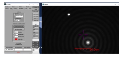
Fig. 6 Transmitted Bessel beam with rings and reflected spot from center of curvature (upper left of crosshair)
From Fig. 6, we know the chuck is well centered because the transmitted Bessel beam core (with rings) and the reflected spot from the center of curvature are in a line through the PSM crosshair. Also the Bessel beam is much closer to the crosshair because the sensitivity of the center of curvature to misalignment is about 3.1 times that of the transmitted beam as shown in Fig. 7, a plot of the spot motions when the seat is misaligned by 50 μm.
If the chuck is not well centered, the chuck is centered against the adjustment screws while tapping the edge of the meniscus to bring the spots on to the crosshair as seen in Fig. 8. As seen in Fig. 7, the spots move in opposite directions for tilt and decenter because of the negative power of the meniscus. This makes it somewhat challenging when performing the alignment because you have to overshoot one adjustment and then compensate with the other. The same thing is true using a rotary table but now you have to remember the azimuth of the table so you make the correction in the right direction. Having no azimuth to worry about makes the challenge easier.
Once the chuck is centered, vacuum is increased to hold the chuck to the glass work surface. Centering the chuck is a one-time setup operation and does not have to be repeated unless the chuck is accidentally knocked out of place. It will be obvious if this has happened because the two spots will no longer be aligned through the crosshair.
The graph in Fig. 7 gives more insight to this operation of centering the chuck. The graph shows the total range of tilt of the lens is about ±3 minutes of arc is more than sufficient to compensate for the 50 μm of decenter of the seat, or chuck. While the spots can be made to coincide (this graph is just for one lateral direction but the same thing happens in the orthogonal direction) they are still about 8 μm from the zero position of the crosshair. Given that the PSM has sensitivity to <1 μm with the standard 10x objective, it is clear that centering the meniscus to 0.5 minutes or better is possible, and about 5 μm in decenter. Since the rings around the Bessel beam give guidance on how to move to bring the core of the beam into the field of view, using a higher power objective with the corresponding increase in sensitivity to improve the centering precision is possible without sacrificing the ease of centering the beam core.
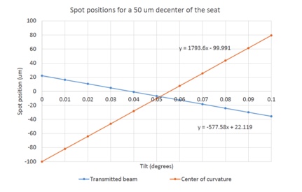
Fig. 7 Transmitted and center of curvature spot motion when meniscus lens is slid on its convex side on the chuck with the chuck decentered by 50 μm.
Once the two spots are centered on the crosshair, the mild vacuum on the chuck is increased to a maximum to hold the meniscus firmly but gently in place. If for any reason, the chuck does not appear to be perfectly centered, the vacuum is lessened and further adjustment made with the centering screws and tapping on the edge of the lens to rotate it in its seat. This completes the centering of the chuck, or lens seat. This method is particularly useful for lenses with a diameter of more than 20-25 mm because another method of centering the seat is to use a ball as described in a previous paper3.
Using a ball is an easier method because there is only one spot, the reflection from the center of the ball. However, when the ball diameter is larger than 20-25 mm there are working distance issues with objective lenses and mechanical interference problems with other parts of the setup. At this point we consider the setup stage complete, and if done with the meniscus lens, the lens is centered on the seat free of tilt. In the case of the ball to center the seat, the meniscus is set on the seat and the center of curvature of the concave side aligned to the PSM crosshair. Again, any misalignment of the seat is obvious because the two spots will not simultaneously align on the crosshair.
5. CENTERING THE LENS
With the meniscus centered and held down with vacuum, a drop of cement is added to the meniscus and the positive element set in place and worked around to squeeze the cement out to the edge of the element all the way around. A reasonable cement thickness is judged by the drag on the positive element as it is moved. Once this is felt like a satisfactory degree of friction the element is centered to the crosshair. Note, the PSM is not moved between the last step and this. We rely on the transmitted beam shown on the monitor to center the positive element as seen in Fig. 7.
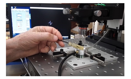
Fig. 8 Final centering of the meniscus element of the chuck. Note 2 adjustment screws for positioning the chuck and 2 vacuum lines, one the hold the chuck to the glass work surface and one to hold the lens in place on the chuck. The 2 spots on the monitor show the centering is nearly complete
With the meniscus centered and held down with vacuum, a drop of cement is added to the meniscus and the positive element set in place and worked around to squeeze the cement out to the edge of the element all the way around. A reasonable cement thickness is judged by the drag on the positive element as it is moved. Once it is felt like there is a satisfactory degree of friction between elements, the positive element is centered to the crosshair. Note, the PSM is not moved between the last step and this. Because the PSM is not moved, there is no longer any conjugate of the cemented lens to focus on in reflection. Instead, we rely entirely on the transmitted beam to center the positive element as seen in Fig. 9 where the single spot is the Bessel beam coming up through the lens in transmission.
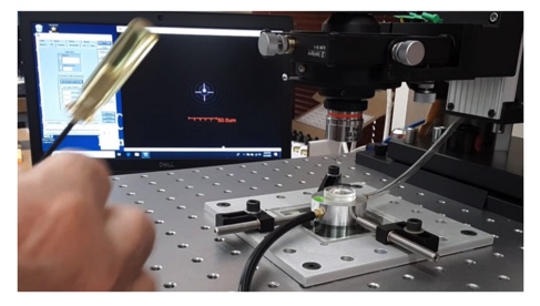
Fig. 9 The positive element almost centered on the meniscus
This final step feels anticlimactic. Other than making sure the cement is sufficiently spread out between the lens elements, there is almost nothing to do. A couple more taps on the lens following Fig. 9 and the lens was centered to about 1 μm. Since the PSM focus is 14.23 mm from the upper positive surface, the 1 μm decenter amounts to a deviation of the gut ray of 70 μradians or about 15 arc seconds. Because the doublet efl was 50 mm, this amounts to a wedge in the lens of about 25 arc seconds assuming an average index for the lens of 1.6. This wedge introduces λ/70 P-V of coma in the lens whose design is dominated by spherical aberration.
6. ALTERNATIVE METHOD OF CENTERING
For small lenses where the chuck is centered with a ball, some people clean the lens halves, add cement and work the cement out with the lens held between the fingers of two hands. This is convenient because the excess cement can be cleaned away before putting the lens on the chuck, and it gives an easy way of inspecting the lens for contamination or bubbles in the cemented surface.
The lens is then set in the chuck, but still the sensitive surface to wedge errors is the cemented surface. In this case, however, we know from Fig. 4 and the text there that this conjugate is only 8 mm above the lens so there is about half the sensitivity to centering errors as with the above method. Further, the meniscus is not centered in the chuck. The two spots, one from the cemented interface and the other from the transmitted Bessel beam are used to both center the meniscus and the lens as a whole. Again, there is an interplay between these two adjustments so that for every lens to be cemented the two adjustments have to be made simultaneously. Finally, because the sensitive conjugate is closer to the lens, the microscope objective is closer to the lens and more in the way of other ancillary operations in the centering.
This is why we prefer the first method described. Once the chuck is centered as a part of the initial setup, every succeeding the meniscus is centered the same way. There are two spots, but since the chuck is centered the spot from the center of curvature of the concave surface, the most sensitive surface for centering, is used to center the meniscus. The transmitted spot will automatically also move to the crosshair because the chuck is centered so effectively you only have one spot to deal with.
Once the meniscus is held down by vacuum the positive element is added. Once the cement is worked out, there is again only one spot to deal with to achieve centration. The first method separates the two centering operations and is more sensitive to errors making the whole process quicker and less tedious.
7. CONCLUSION
We have described two methods of precision cementing of doublet lenses that do not require a rotary table to establish a centering axis. One of the methods, first aligning the meniscus element, and then adding the positive one is more sensitive to alignment errors and less tedious. Both methods benefit from having the adjustments made from a fixed platform rather than a rotary table. The elimination of extraneous adjustments introduced by the rotary table make the centering process without the rotary table more productive because it is faster and more intuitive.
REFERENCES
[1] Heinisch, J., Hahne, F., Langehanenberg, P., Rotation-free Centration Measurement for Fast and Flexible Inspection of Optical Lens Systems, Proc. SPIE, 11175, 111751B (2019)
[2] Parks, R., Alignment using plane Axicon gratings, Proc. SPIE, 10747, 1074703 (2018)
[3] Parks, R., Design for Alignment, Proc. SPIE, 11103, 1110302 (2019)
[4] Zhao Bin and Li Zhu, “Diffraction property of an axicon in oblique illumination,” Appl. Opt. 37, 2563-2568 (1998).
[5] https://optiper.com/en/products/item/point-source-microscope