When most people think of a microscope it is one that works in transmission with the light source on one side of the sample and the microscope objective and eyepiece on the other. An autostigmatic microscope (ASM) works in reflection, just like an autocollimator, so the light source is in the microscope body, and is almost always introduced via a beamsplitter close to the objective but between objective and eyepiece as shown in Fig.1.
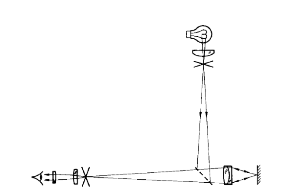
Fig. 1 An autostigmatic microscope (from Steel[1])
An ordinary reflecting microscope such as one used to examine opaque samples uses an extended light source that is imaged on the entrance pupil of the objective so that the light is made to uniformly flood the sample over the microscope field of view. An autostigmatic microscope is different in this respect in that a crosshair or pinhole source of light is placed conjugate, via the beamsplitter, to the eyepiece object plane. This means that an image of the crosshair or pinhole will be in focus at the focus of the microscope objective. In some very simple cases, the coiled filament of the light bulb making up the source is conjugate to the eyepiece object place so that when the microscope is focused on a surface the filament is in good focus viewed through the eyepiece.
This rather long description of an ASM is necessary because there are almost no literature references to them yet they are a staple in almost every optics shop for use in measuring test plate, or lens surface, radii of curvature. The only literature reference I have found is a paper1 by W. H. Steel titled “The Autostigmatic Microscope”, although he cites a reference to C. V. Drysdale2 in 1900, “ON A SIMPLE DIRECT METHOD OF DETERMINING THE CURVATURES OF SMALL LENSES”. Drysdale started the Technical Optics Department at Northampton Institute in that same year, so it is clear ASMs have been around for over a century.
Going back to Steel, his paper describing an ASM was probably written for the same reason as this paper, his audience had very little idea what an ASM was and what it was used for. His audience happened to be optometrists because he was working at CSIRO, the Australian version of the US NIST, on a job to measure the radii of curvature of contact lenses back in 1983. In the abstract to the paper he stated “The autostigmatic microscope is an instrument for measuring the line-of-sight distance to areflecting surface and is used chiefly to measure the radii of lens surfaces.”, and goes on to say the ASM is an analog of an autocollimator that focuses at a finite distance rather than infinity.
The one other place I have seen mention of an ASM is in Warren Smith’s book, “Modern Optical Engineering” toward the very end where he calls it an autocollimating microscope3 and ascribes to it the same use as Steel. The implication in Malacara’s Optical Shop Testing4 is that one would obviously use an ASM in many cases of testing but ASMs are never mentioned explicitly.
How the ASM works
Before going further we should explain how the ASM works in the two modes used to measure radii. The principles are most easily explained by considering the light source as a pinhole conjugate with the object plane of the eyepiece. In this case, an image of the pinhole will appear at the objective focus and be smaller than the pinhole source by the magnification of the objective. If the pinhole source was 50 μm in diameter, it would appear as 5 μm in diameter at the focus of a 10x objective. Also note, as in Fig. 1, microscopes in the time frame of Steel’s paper used finite conjugate objectives so the objective was the only optical element with power in the microscope. This is a perfect example of a stigmatic optical system, one that images a point of light in the object plane into a perfect point in the image plane.5
If the ASM was focused on a specular surface as in Fig. 2, the light coming from the top part of the objective would reflect off the surface and re-enter the objective at the bottom, and vice versa. This is the so called Cat’s eye, or retroreflection, focus. Notice that the surface does not have to be normal to the optical axis of the objective, the reflected light will always return to the pinhole source on the other side of the meridional plane from which it started out. The reflecting surface can be tilted from normal until none of the reflected light makes its way back into the objective, but whatever light does make it into the objective will always focus on the source pinhole.
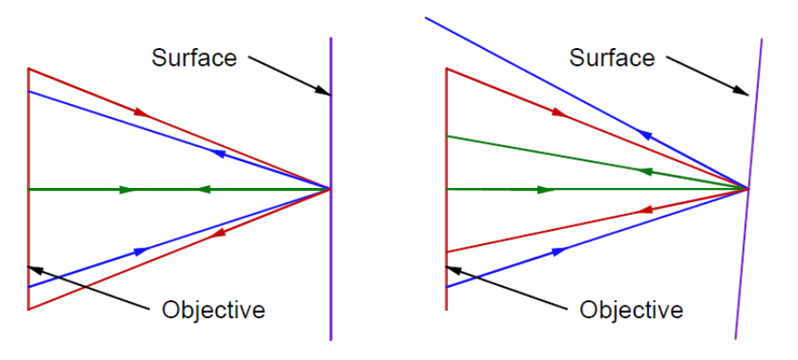
Fig. 2 Cat’s eye reflection with surface normal to optical axis of objective (left) and with surface tilted (right)
As a consequence of this retroreflection behavior, the reflected light passing through the beamsplitter to the eyepiece will always focus in the same place laterally in the eyepiece object plane, and this place is exactly conjugate to the pinhole light source. If the objective is not in good focus on the surface the reflected spot will be out of focus but always centered in the same location independent of the tilt of the surface. At best focus the image in the eyepiece object plane will be exactly the same size as the pinhole in the source. Notice that this is the same type of behavior as putting a cube corner reflector in front of an autocollimator, the reflected light spot is stationary even when the cube corner is no longer square with the axis of the autocollimator.
The other location where reflected light returns to the ASM is if the focus of the objective is at the center of curvature of a spherical surface as in Fig. 3a where the objective is focused on the center of the ball, here used as a convex mirror. Light rays exiting the objective follow normals to the surface of the spherical ball, and light is reflected back along the normals into the objective. If, however, the focus of the objective is slightly to the side of the center of curvature as in Fig. 3b, the return light will focus on the opposite side of the center of curvature. This makes the ASM very sensitive to alignment with the center of curvature of a spherical surface. Obviously, just as in the case of the Cat’s eye reflection the return spot of light will be out of focus if the objective focus is not coincident with the center of curvature along the line of sight to the surface.
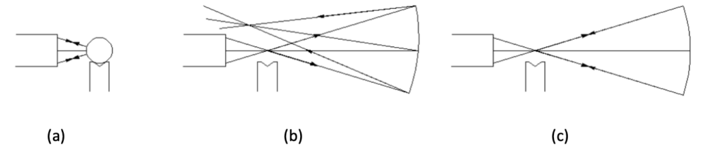
Fig. 3 Objective focused at the center (of curvature) of a ball, or convex mirror (a), focused near the center of curvature of a concave sphere (b) and focused precisely at the center of curvature (c)
With this background it is now easy to see how an ASM can be used to measure the radius of curvature of a lens or mirror surface. First focus the ASM on the surface near its center and the Cat’s eye reflection will appear in good focus when the ASM is precisely focused on the surface. Adjust the cross hairs or other reference in the eyepiece on the return spot as this reflected image is at the conjugate of the light source, and on the optical axis of the ASM.
Then move the ASM to focus at the center of curvature of the surface by aiming the ASM roughly at the center of the surface and moving in 3 degrees of translation until the return reflected spot lies centered on the eyepiece crosshairs or reference. The ASM is now precisely located at the center of curvature in 3 degrees of freedom. Note the position of the ASM base on a rule or straightedge lying between the ASM and surface. Move the ASM along the straightedge until the Cat’s eye reflection is again in focus and note the scale reading. The difference in the 2 readings as shown in Fig. 4 is the radius of curvature of the surface. Note that by moving along a straightedge from a position where the ASM was centered at the center of curvature means that the ASM is moving along a normal to the sphere and a true reading of the radius of curvature will be achieved.
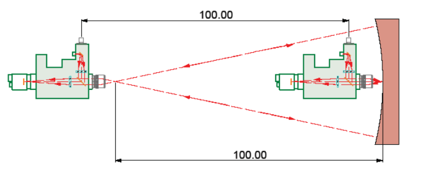
Fig. 4 Use of an ASM to measure the radius of curvature of a concave mirror
Notice also that this method works equally well for convex surfaces as long as the objective has a long enough working distance to accommodate the radius of the surface. Another issue to keep in mind is that the laws of physics still apply to radius measurement. If the surface being measured has a small diameter relative to its radius of curvature there will be difficulty finding best focus due to the slow f/# of the light cone. On the Cat’s eye side, a higher magnification objective permits greater sensitivity to focus but at the center of curvature may throw away too much light beyond the edge of the surface. In general, use a low magnification objective like 5x for slow surfaces and a 10 or 20x objective for fast surfaces.
My introduction to autostigmatic microscopes
My first job after getting out of school with a MA in Physics and no formal optics education was at Eastman Kodak Company. Virtually the first thing they had me do was measuring the radius of curvature of test plates, the master surfaces against which lens surfaces would be checked using Newton ring interference. The measurement was done with an ASM whose make I forget but it could have been one from Gaertner Scientific6, a company that still sells all the parts needed to make an ASM. Another project at Kodak got me into issues of aligning one optic to another but the idea of using an ASM as an alignment device did not click in my mind.
From Kodak I went to Itek Corporation (now a part of Goodrich) in Lexington, MA. One of my jobs there was to adjust the 6 cameras in the S-190 survey instrument7, flown on Skylab in the summer of 1973, for matched distortion and magnification. Each camera operated in a different spectral band and the idea was to be able to overlay the 70 mm format negatives from the different cameras and have details in the film match up to +/- 1 μm. This meant each nominally 150 mm focal length camera had to beadjusted to have nearly identical field heights at the edges of the field even though some of the spectral bands were outside the visible spectrum into the IR.
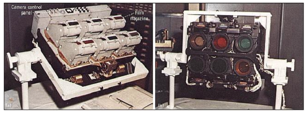
Fig. 5 S-190A Multispectral Photographic Camera System
We used a nodal slide lens bench to do the measurement and projected a collimated beam of white light from a pinhole source into each of the cameras. The point images in the camera focal planes were detected with a microscope that had a quad cell photo detector in the eyepiece object plane. There was a beamsplitter so that the images could be viewed either visually or electronically. The visual image allowed us to get things aligned initially but the data were taken for all 6 cameras using the electronic quad cell so all the distortion and magnification data were all treated the same. This use of a microscope with an electronic detector put another piece of the ultimate ASM design in the back of my mind.
From Itek I went on to work at Frank Cooke, Inc. in central Massachusetts and learned how optics were really made instead of just testing them. One of the items made there was a hyper-hemispherical glass dome about 180 mm in diameter and 6 mm thick. There was a reasonably tight spec on the concentricity of the inner and outer surfaces of the dome, that is, the centers of curvature of the 2 surfaces were supposed to be within 50 μm of each other in all 3 degrees of freedom.
The person in charge of testing at Cooke’s was Raymond Boyd who had formerly worked for American Optical in Southbridge, MA. To test for concentricity, Ray effectively made an ASM by inserting a piece of optical fiber in a filar eyepiece much as in Fig. 6.
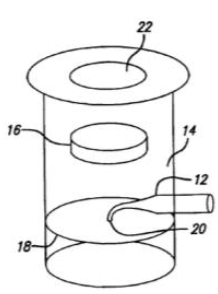
Fig. 6 Illustration from US Patent 6,924,897 showing an eyepiece with a fiber point light source. 12 is the fiber preform, 20 the drawn out tip, 18 the eyepiece focal plane and 16 the eyepiece lens
Ray had worked with Elias Snitzer, one of the early inventors of fiber optics at American Optical, and had access to fiber optic pre-forms that were about 3 mm in diameter. Ray would use an alcohol flame to draw the preform out into a small diameter fiber and bend the tip 90 degrees to make a rudimentary point source. He used a microscope illuminator focused on the large end of the preform as the light source. When the fiber tip was at the centers of curvature of the dome, point images were returned from both surfaces and the distance separating them could easily be measured with the filar scale in the eyepiece focal plane.
This simple optical device could do in minutes what would otherwise be a complex mechanical metrology problem requiring a good rotary bearing and several contact measurements along with some math to determine the same knowledge of the concentricity of the surfaces. We used similar fibers to test such things as fast elliptical reflectors as described in a brief paper8 I wrote after moving on to run the Optics Shop at the Optical Sciences Center at the University of Arizona.
While at Optical Sciences I found that EG&G was making an eyepiece for a radiometric instrument they sold that was almost identical to the one Ray Boyd had used at Cooke’s. EG&G used the eyepiece backwards to how we intended to use it; the tip of the fiber picked up light coming toward the eyepiece from the sample being viewed and a fiber bundle took that light to a sensitive photometer to record its value. We illuminated the end of the fiber bundle with a bright source and let the light exit the tip in the eyepiece headed out of the microscope through the objective. When the objective was focused on a specular surface the light from the fiber came back in retroreflection directly on the fiber tip in the eyepiece. This was a great, commercially available, solution to making a point source eyepiece for an ASM. Unfortunately, not many years later EG&G stopped making these eyepieces.
About this time I left the University to start a consulting company called Optical Perspectives Group, LLC along with a colleague, William P. (Bill) Kuhn. One day we got call from a local company that had designed a complex lens for a laser writer system they were making. The system had 6 lenses, some of which were rectangularly edged toroids, and a spherical mirror, all of whose centers of curvature were supposed to lie on a straight line. Our job was to come up with a method of aligning the lenses and mirror so this was the case.
We immediately recognized this was a perfect job for an ASM which we put together with Thorlabs parts and an analog CCD camera. The ASM was mounted in the chuck of a milling machine and the optical bench holding the lens elements was set on the mill table that we used as a large x-y-z stage. With this set up we were able to get to the centers of curvature of all the elements by cranking the mill table over the length of its travel. In the case of the toroidal lenses we would get back line images instead of a circular spots but the lines were just as easy to align as the spots.
Using this crude ASM and the mill we were able to align the lens system in about 4 hours and get better performance from the system than they had previously by another method that took about 2 weeks. The company was delighted, but the system needed to be assembled in a clean room environment and they could not put the mill in the clean room.
This was the beginning of the original Point Source Microscope (PSM), an ASM small and light enough to be held on the ram of a coordinate measuring machine (CMM) in place of the usual mechanical touch probe. Many advances in technology had been made over the years since the ASM put together at Cooke’s. There were affordable CCD cameras and single mode fiber light sources in the visible. Also, microscope design had changed from a finite conjugate to infinite conjugate version where the lightbetween the objective and “tube lens” was collimated. The reason for this change was that it made customizing microscopes much easier since the distance between the eyepiece and objective did not have to stay fixed. It also meant that in reflecting microscopes the beamsplitter that was necessary to introduce the light from the source no longer introduced aberrations into the converging beam of light in finite conjugate microscopes.
The initial major problem with the new PSM was there was no easy way to mark where the Cat’s eye reflection returned on the detector. Our initial solution was to place a Magic Marker dot on the analog monitor faceplate. This worked but was neither elegant nor precise. We then realized that a Shack cube, such as used in a Shack cube interferometer9, would be just what was needed to produce a reference spot of light to be the indication of where to bring the light to focus from the center of curvature of the surface we were trying to align. Fig. 7, taken from US Patent 6,924,897, shows the original PSM layout and the Shack cube (#30).
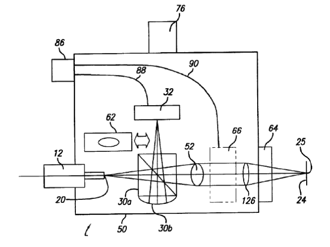
Fig. 7 Layout of the original Point Source Microscope
The Shack cube is a cube beamsplitter with plano-convex lens cemented to one side so that its center of curvature is conjugate to the tip of a single mode optical fiber (20) and the analog CCD camera. The objective is #126 and the tube lens is #52 with collimated space in between. While this design worked very well for our customer, we realized almost immediately that this was not a very smart design; once the return spot was centered behind the reference spot there was no way to center any better. This limited our centering ability to about 5 μm. At the same time useful technology was moving forward at a fast pace.
Bill looked at a combination of the short comings of this original design and advances in technology to come up with what is now sold as the PSM, and is shown schematically in Fig. 8. There are many improvements on the original but the one to address the major flaw of the first was to use a digital CCD camera coupled with National Instruments LabView software that could centroid on the return spot of light. This meant that when the Cat’s eye spot was first obtained in good focus the software could place an electronic crosshair on the video display to define the lateral zero position on the display to a fraction of a μm. Other return spots could then be located relative to the crosshair to the same precision.
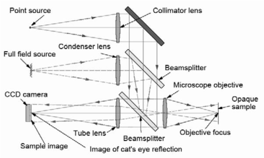
Fig. 8 A schematic diagram of the optical paths within the PSM
Going back to Fig. 8, other new features included an internal LED light source and diffuser to provide Kohler illumination for full field imaging so the PSM could be used as an ordinary video microscope as well as an autostigmatic one for alignment purposes. Where the original PSM had an external fiber source the new one has a single mode fiber pigtailed to a red laser diode. The two light sources are adjusted so the autostigmatic focus is parfocal with the full field image plane. Another feature of the laser diode light source is that it has a bright and dim mode. In the bright mode the light is bright enough to be seen under ambient lighting so that it is easy to find the return reflected light spots. However, this intensity is sufficient to saturate the camera in most cases so the dim mode is used for the electronic centroiding.
A further feature is the use of infinite conjugate optics so that when the objective is removed from the PSM it becomes an autocollimator. Thus the PSM is 3 distinct instruments in one, a video imaging microscope, an ASM and an autocollimator with an exceptionally large angular capture range.
Using the PSM for alignment
Now that the development of the PSM and the use of it to measure radii of curvature have been described, we will describe a simple but non-trivial alignment situation. Assume we want to align the optics in a 2 mirror grating spectrometer that, when aligned, looks like Fig. 9. We will assume that the 2 slits and the axis of the grating are fixed by the mechanics of the lens bench on which the optics are mounted. From a combination of the mechanical and optical drawings of the instrument we know where the centers of curvatures of the collimating mirrors should be relative to the slits and grating axis before the optical path is folded to the slits. Further, the 2 fold mirrors should be set so that light focused at the entrance slit exits in focus at the exit slit. Also assume that all 4 mirrors that will be aligned are held in mounts with 3 adjustment screws so they may be tilted in 2 directions and displaced axially in the direction of the screws by turning all 3 simultaneously.
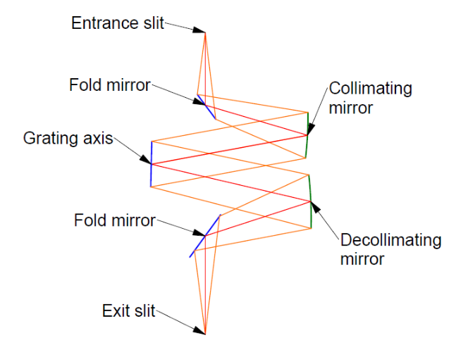
Fig. 9 A two mirror grating spectrometer in its final configuration
Fig. 10 shows where the centers of curvature of the collimating mirrors are (violet) and where they are reflected in the fold mirrors (blue) when the fold mirrors are properly aligned.
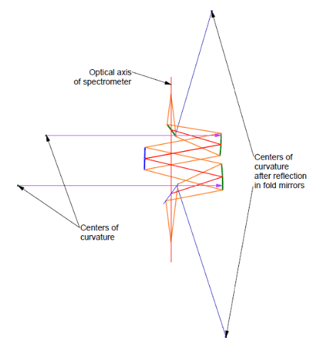
Fig. 10 The center of curvature locations of the collimating mirrors directly and as folded
To perform the alignment the optical bench on which the mirrors and grating are mounted are temporarily mechanically pinned to an alignment fixture plate into which holes have been bored at the center of curvature and slit locations. Into these holes a post is placed on the top of which is a spherical steel ball. An example of this type fixture is shown in Fig. 11 where the posts are lens mount posts and the balls sit kinematically located in the conical chamfer in the posts. A collar on the post keeps the distance above the fixture constant.
In Fig. 11 the PSM is focused on the center of a steel ball located where the center of curvature of the relay mirror in the black optical bench should be located relative to the bench as defined by the aluminum plate fixture and the pinning of the bench to the alignment plate. This approach permits the alignment to tolerances that are as good as the balls can be located mechanically.
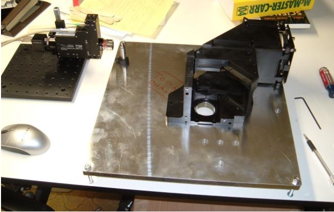
Fig. 11 The PSM focused on the center of a steel ball sitting on the post located in the bored hole in the aluminum alignment plate.
In the case of the spectrometer the same approach is used. First a post and ball are placed at the center of curvature of the collimating mirror. The PSM on a 3 axis stage is placed facing the mirror and adjusted until the objective focus is at the center of the ball in all 3 degrees of translational freedom. Half inch diameter, Grade 5 steel balls are excellent convex mirrors. The ball is removed from the post so the light from the objective illuminates the mirror and is refocused near the objective focus. The 3 screws on the mirror are used to bring the center of curvature of the mirror to the precise focus of the objective in all 3 degrees of freedom. This is why 3 adjustment screws are needed on the mirror so that the mirror can be adjusted not only in 2 angles but axial translation to get best focus as well.
This step is repeated for the decollimating mirror. The post is moved to that hole in the plate, the PSM is moved over and focused on the center of the ball, the ball is removed, and the mirror adjusted with the 3 screws. Note how the PSM is used to place an optical conjugate that cannot be touched physically in proper relationship to a feature that is mechanical and can be touch probed mechanically. The PSM is a transfer device from an ethereal optical conjugate to a rigid mechanical datum, or vice versa.
Now the fold mirrors can be adjusted by using holes located where the centers of curvature should appear as reflected in the correctly adjusted fold mirrors. In Fig. 11 there are a set of 4 holes toward the front edge of the alignment plate. The hole nearest the edge of the plate is where the center of curvature of the relay mirror is after the fold mirror is installed in the black optical bench. The idea is the same for the spectrometer. The PSM is set up facing the fold mirror and centered on the ball. The fold mirror is then adjusted in 3 degrees of freedom until the center of curvature is centered on the PSM focus. Notice that it takes 3 adjustments on the plane fold mirror to accomplish this alignment.
Once both fold mirrors are adjusted a post and ball can be placed where the exit slit is to go, and the PSM aligned to a ball at the entrance slit as in Fig. 12. Only if the grating is adjusted so the double pass reflection of the entrance slit lies on the exit slit will light return to the PSM focus. This 0 order reflection from the grating establishes the zero angle setting on the grating rotation axis and allows a correction for any tilt in the orthogonal direction.
Another aspect of this final alignment is that the return spot to the PSM will not be a perfect spot but will be aberrated due to the optical design of the spectrometer. But the aberrated spot should be of a size and shape consistent with the design of the spectrometer. If it is not the expected spot it is clear something is wrong with one or more of the optics. Actually, at each previous step in the alignment a serious figure error in any of the optics will be noticed. The PSM has the ability to sense asymmetry in the image down to a level of 1/8th to 1/10th wave. If there are figure errors of these magnitudes, they will be apparent in the “Star test” image10, 11,12 as each of the optics is aligned. This means that errors in assembly can be caught before the entire system is put together, and before having to figure out which element is to blame for the lack of system performance.
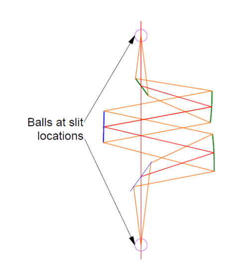
Fig. 12 Check of the grating zero angle by double passing the spectrometer off a ball at the exit slit
Conclusion
We have explained what an autostigmatic microscope is, and how it can be used for measuring optical surface radii. I have also described how a modern version of an ASM was developed over a number of years as my familiarity with its use expanded and as technological advances were made in many useful components that became part of the final Point Source Microscope. Finally we showed an application of using the PSM for alignment of optical components and showed how an ASM acts as a transfer device from ethereal optical conjugates to fixed mechanical references.
References
1 Steel, W. H., “The Autostigmatic Microscope”, Optics and Lasers in Engineering, 4, 217-27, (1983).
2 Drysdale, C. V., “ON A SIMPLE DIRECT METHOD OF DETERMINING THE CURVATURES OF SMALL LENSES”, Transactions of the Optical Society of London, pp. 1-12, 1900.
3 Smith, W. J., Modern Optical Engineering, 3rd ed., McGraw-Hill, New York, (2000), p. 584.
4 Malacara, D., Optical Shop Testing, 3rd ed., Wiley & Sons, NJ, (2007).
5 Korsch, D., Reflective Optics, Academic Press, San Diego, CA, (1991), p. 15.
6 Gaertner Scientific, https://www.gaertnerscientific.com/microscopes/main.htm
7 https://directory.eoportal.org/web/eoportal/satellite-missions/s/skylab
8 Parks, R. E., “Optical tests using fibers, balls and Ronchi gratings”, OSA OF&T Workshop, Mills College, Oakland, CA (1980).
9 Smith, W. S., “Versatile interferometer for shop use,” Proc SPIE 192, 16 (1979).
10 Malacara, op. sit., pp. 398-420, particularly pp. 418-9.
11 Richard, H., Star testing astronomical telescopes, William-Bell, Inc. (1997) pp. 9-13.
12 Parks, R. E., “Using image symmetries to uniquely align aspheric mirrors to a focus and axis”, Proc. SPIE, 12222, 1222205 (2022).