ABSTRACT: Talk is largely tutorial by has a two-fold motivation Definitions of kinds of alignment
Initial alignment steps to get light into alignment sensor-autostigmatic microscope, alignment telescope or interferometer Systematic alignment steps using the alignment sensor. Good idea to have a written procedure because many steps Alignment results using real hardware.
Robert E. Parks, Benjamin F. Anjakos
Optical Perspectives Group, LLC Tucson, AZ 85750
Steward Observatory, Univ. of Arizona Tucson, AZ 85721
Optomechanical Engineering 2023 SPIE Optics and Photonics
20-25 August 2023
Background and motivation
- Work on a project where alignment was critical
- Discussions with optical engineers without much hands-onexperience in alignment, had little idea of how well they couldposition hardware – saw need for a procedure
- Connection between image symmetry and kinematics of alignment
- Writing a blog on alignment that might become a book
- Awareness of new software to make alignment more quantitative
(My) definitions of alignment
Hard alignment – uses centers of curvature, reticles at vertices and foci
Reflected centroid identified to the ± 1 μm level in 3 degrees of freedom (DOF)
Soft alignment – centering the test wavefront on the aperture of the article under test Usually fine if centered to a couple of degrees, often eyeball is good enough
Alignment with aberrations – centers of curvature and vertices difficult/impossible to reach optically
Forced to rely on aberrations for alignment
3 degrees of freedom (DOF)
5 DOF – 3 at focus, 2 at flat
Initial steps to get light into alignment sensor
- Set the x-y axis origin of the sensor using a Cat’s eye reflection
- Provide mounts with sufficient range of motion and DOF for alignment
- Position mounts with elements as close as possible mechanically
- Use a low power objective or reduce aperture of transmission sphere initially
- Adjust point source of light to produce expected behavior on first reflection
- Adjust return mirror to center reflected beam on sensor aperture
- Adjust return beam focus to outgoing focus
- Perform systematic alignment using quantitative feedback from sensor
Set x-y axis origin in sensor
To eliminate retrace error the reflected path must overlay the outgoing path
This is effectively boresighting the alignment sensor
Use a Cat’s eye reflection from a specular surface at the focus of the sensor Interferometers have built in functions to help with this, rotation serves this purpose with
alignment telescopes and autostigmatic microscopes centroid electronically
Tilt fringes in an interferometer are the analog of an image being decentered in an AT or ASM
Mounts for optical elements
Mounts must have the necessary DOF to achieve alignment, but no more than necessary
Too many adjustments make alignment confusing
Mounts need the necessary range of travel but be sensitive to adjustment at alignment level May need actuators if touching by hand introduces unacceptable errors
Adjust mounts to mid-travel range, if possible, before screwing to table
Mounts must be stable, screwed to table – stacks must be kinematically secure Use spacers at 3 points to assure kinematic stability
Locate mounts precisely mechanically
If possible, make optical axis of the alignment setup parallel to table top
The centers of all apertures are the same height to 1 mm or less
As the axis height reference, use the component with the least flexibility to adjust
An interferometer would be a good example of inflexibility Use the tapped holes as a guide in the plane of the table
Use a plastic ruler to help position mounts
Don’t be afraid to use a Sharpie to mark locations – it wipes off with alcohol Add mounts one at a time starting at the source to get optical path started correctly
Alignment is paraxial – use low NA beam initially
Just as when using a microscope, start with the least powerful objective
Find area of interest, and switch to higher power while keeping object centered
Easy to start with a low power objective with an ASM because objectives are parfocal Transmission sphere are not parfocal, use one that overfills the aperture Lower the NA by masking the transmission sphere
Once alignment is reasonably good, change objectives and remove mask to fill aperture Using aberrations forces the use of the full aperture
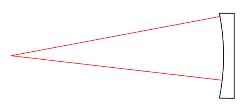
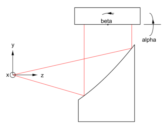
Keep components as close together as possible
As in the picture keep the flat close, initially
This reduces the beam translation due to small angular errors in alignment
Once source and parabola well aligned, flat can be moved away because alignment is fixed
If return mirror has power, it must be located at the proper spacing
Using the low power objective or stopped aperture helps in this case
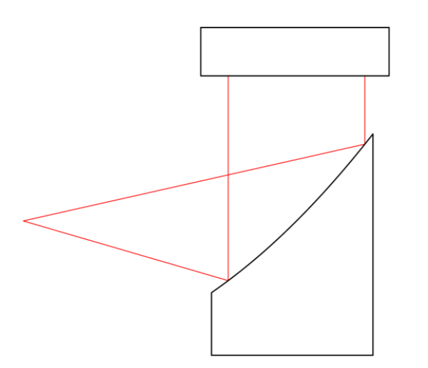
Adjust source relative to the first surface
Before adding the flat, look at the reflected beam for collimation and symmetry Use a bright source and white card to view the reflected beam
Since it is a parabola, the beam should remain reasonably well collimated
If not, adjust source distance from parabola until it is Reflected beam cross section should be round moving away from the parabola
If not, move the source in x-y to improve roundness
Adjust the return mirror to follow the beam back to source
With the return mirror in place, adjust it in tip/tilt to make the reflected beam follow the outgoing Probe the edges of the beam and tilt the mirror to overlap the 2 beams
If the alignment is anywhere close the reflected image should be near the outgoing focused spot Leave a little lateral misalignment to find the return image
Adjust focus of return spot to the same plane as the outgoing spot
Finally, overlap the images and the return image should be visible in the alignment sensor
Adjust the return mirror to center image
This is the beginning of the quantitative alignment
First adjust the return mirror, or the alignment sensor to center the spot on the crosshair Adjust focus to what appears best focus and adjust camera gain to 1/3 total range
Want to avoid saturated pixels at best focus when well aligned
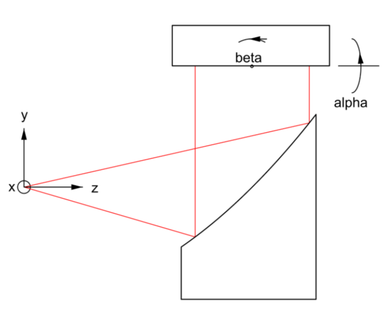
Alignment methodology
Must keep image centered on crosshair to avoid retrace error
Means making compensating tilt and decenter adjustments to reduce image size Along with keeping sensor adjusted for best focus
With the 90° parabola the main aberration is astigmatism First alignment step is to check for best focus Astigmatism rotates 90° on either side of best focus Check sign or orientation of astigmatism with focus
Good idea to have written procedure and to make notes Next chart shows alignment steps
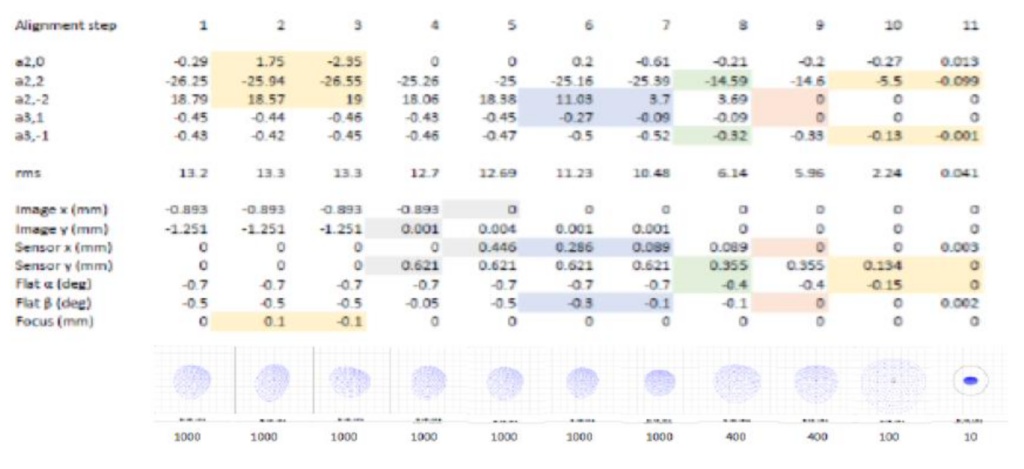
Change in Zernike coefficient with alignment step
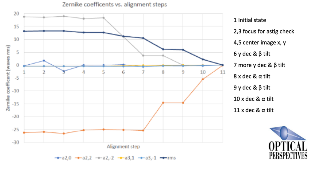
Change in alignment and image with each step
Alignment using real hardware and image symmetries
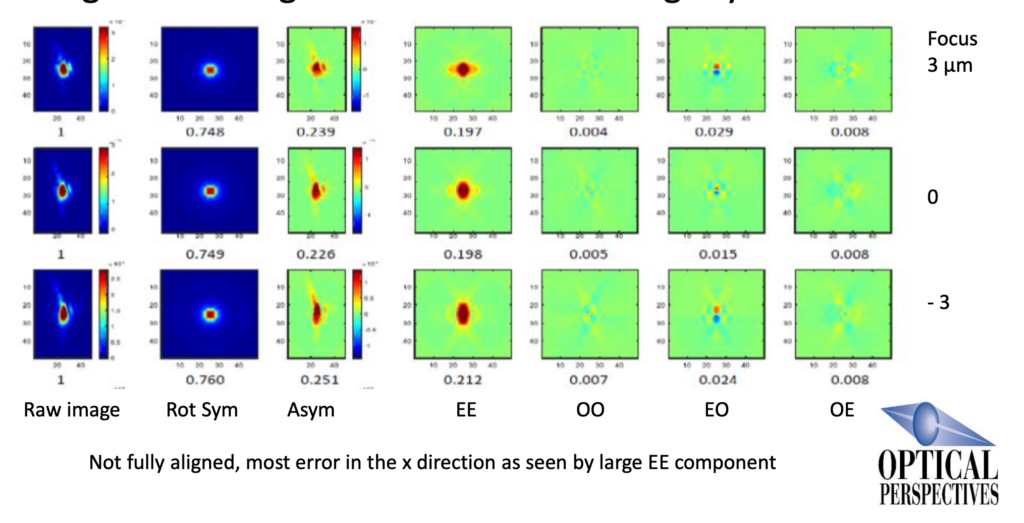
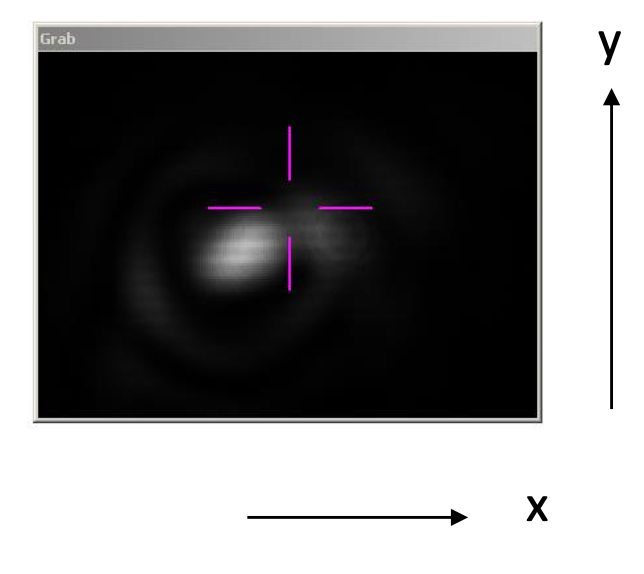
Concluding observations about the images
Obviously diamond turned surface – horizontal diffraction patten (Oversaturated to show diffraction)
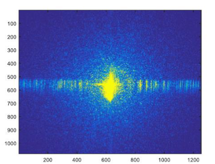
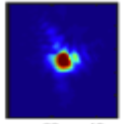
Irregularly shaped image indicates mid-spatial frequency errors
Conclusions about alignment with aberrations
Showed some simple methods of making initial alignment easier
Showed making compensating adjustments keeping image centered
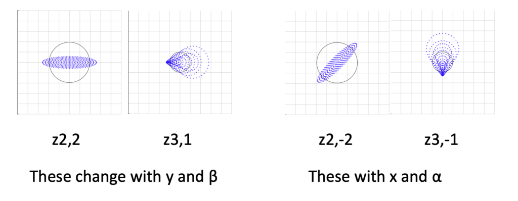
Showed how 5 adjustments match 1:1 with 5 image symmetries
Showed how image symmetries guide which adjustment
Showed sensitivity of image characteristics to alignment
References
Parks, R. “Using image symmetries to uniquely align aspheric mirrors to a focus and axis”, Proc. SPIE, 12222, pp. 24-32 (2022).