Versatile Autostigmatic Microscope
ABSTRACT
An autostigmatic microscope is described and its uses explained. Then an adaptation of the original instrument is described that uses current technological advances in laser diodes and video displays to turn an old workhorse into a versatile optical test and alignment device. This paper illustrates applications that make use of the capabilities of the modern autostigmatic microscope outside the field of aligning optical systems such as using it as an electronic autocollimator, a check on the centration of the axes of molded optics and the measurement of the runout and wobble of precision spindles such as air bearings.
1. INTRODUCTION
First we will describe what an autostigmatic microscope (ASM) is and how it has traditionally been used. Then we will describe the features that make this modern realization of an autostigmatic microscope have applications far wider than the traditional ones. Finally we give examples of the use of this modern adaptation to demonstrate the versatility and practicality of the instrument outside the areas strictly concerned with alignment.
2. DESCRIPTION OF AN AUTOSTIGMATIC MICROSCOPE
2.1 Definition of an autostigmatic microscope
We all know what a microscope is; an optical instrument with an objective lens designed to produce images of objects located a short distance from the objective at a high magnification, or at large image distances. This means there is a fast f/number cone of light on the object side of the objective lens and a slow cone on the image side. “Stigmatic” means that the objective lens images well.1 A point source of light at one conjugate of the objective forms a cone of light at the other conjugate where all the rays cross at a single point, particularly on axis.
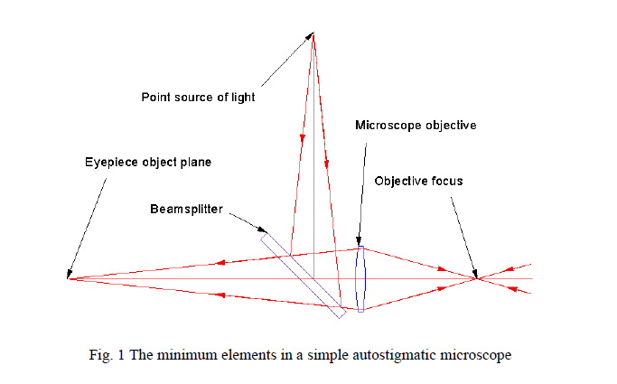
This leaves the word “auto”. The autostigmatic microscope (ASM) is analogous to an autocollimator except that instead of sending out a perfectly collimated beam of light and having a means of detecting the angle of the return light beam, the microscope sends out a perfectly focused cone of light and has the means of detecting the lateral position and focus of the return spot or stigma of the cone of light. Fig. 1 shows the necessary components of a simple ASM microscope. A point source of light is reflected from a beamsplitter into a microscope objective that forms a perfect axial focus and the light diverges to the right. Perfectly focused light converging from the right to the objective focus would be stigmatically imaged at the center of the eyepiece object plane at the left.
2.2 Traditional uses of an autostigmatic microscope
To understand the traditional uses of an ASM it is again helpful to think of an autocollimator. An autocollimator is an instrument that measures the angles of plane surfaces using the light reflected off of them at near normal incidence and is helpful in seeing what the angular relationship of one surface is to another. The ASM is an instrument that measures the location of the center of curvature of a spherical surface using light reflected off the surface at, or near, normal incidence, and is helpful in relating the position, in three dimensions simultaneously, of one center of curvature to another. Since the alignment of optical systems is really about placing centers of curvature where an optical design specifies they should be, an ASM is useful for the alignment of optical systems.2,3
2.3 The utility of an autostigmatic microscope
Even this very simple autostigmatic microscope is more useful than an autocollimator in that it can also measure the radius of curvature of a spherical surface when attached to a linear scale. Fig. 2 shows two examples of this, one for the more familiar case of a concave spherical surface and the other for a convex surface. The reason the ASM can measure the radius of curvature is that when the focus of the objective is coincident with a surface, a Cat’s eye reflection is produced off the surface. This is illustrated in the right hand side of Fig. 2 in the plane of the page where light coming out of the top of the objective aperture is reflected off the surface. The angle of incidence equals the angle of reflection and so the light returns into the bottom of the objective aperture. Obviously the same thing happens symmetrically around the objective aperture but is not shown for clarity.
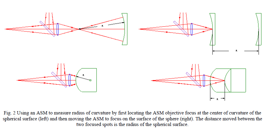
The axial distance the microscope is moved between the positions where the return spot in the eyepiece object plane is in sharp focus is the radius of curvature of the spherical surface. If the radius of the convex surface is larger than the working distance of the objective, an auxiliary positive lens with a object distance longer than the radius must be used to relay the center of curvature. Although this measurement looks like simplicity itself, making the measurement accurately to better than 1 part in 1000 is not easy without attention to detail that has little to do with the ASM itself.4,5
Returning to the discussion of the Cat’s eye reflection, notice that the light coming out of the objective at an angle α with respect to the axis of the objective returns at -α independently of the tilt of the surface until the tilt is so great no light gets back into the objective, or is completely vignetted. This means the center of the return spot will always be in the same position in the eyepiece object plane regardless of the tip or tilt of the surface. Because of this feature of a Cat’s eye reflection no information is known about the tilt of the surface, only whether the surface is in focus as evidenced by the smallest possible spot diameter as seen in the eyepiece or a CCD camera located at the long conjugate of the objective. For this reason the Cat’s eye lateral location is a perfect “zero” lateral reference.
2.4 Relative scarcity of autostigmatic microscopes
It is clear from the brief discussion above that ASM’s are useful and, in fact, are used in most optical shops for measuring the radii of optical surfaces. Most of these ASM’s were built before laser diodes were common and use either a projected reticule illuminated by an incandescent bulb or a bulb filament as the light source, both of which are extended sources, not very bright and not particularly good for centering. They are fine instruments for finding focus at centers of curvature (once you find the dim return spot) and surfaces.
One of the things that has happened since most of these ASM’s were put in service is that there are now virtually perfect light sources for ASM’s, namely single mode, fiber pigtailed, laser diodes. These are bright (many mW’s), nearly monochromatic, visible (635 nm), small Gaussian spots (~4.5 μm single mode field diameter) with a divergence of about f/5 at the beam waist. In addition the laser diodes are relatively inexpensive, they last forever and their intensity is easily controlled remotely. The small size of the single mode fiber source means that the focused spot exiting the objective will be diffraction limited for any decent microscope objective (assuming the rest of the optics in the microscope are high quality).
Another thing that has happened relatively recently is that there are small, digital, CCD cameras available at a reasonable price that can be easily interfaced with computer displays. This is particularly advantageous when using a laptop computer because the display can be located close to the ASM so what would ordinarily be viewed through an eyepiece can now be viewed in a much more ergonomic fashion right along side the instrument being tested or aligned. This also aids hand/eye feedback while making alignment adjustments.
In addition, someone had to take these new devices and package them along with custom software to drive the laser diodes and control the camera. Our company, Optical Perspectives Group, and principally, Bill Kuhn,6 has done just that. Optical Perspectives Group7 markets this new ASM as the Point Source Microscope or PSM.
3. DESCRIPTION OF THE POINT SOURCE MICROSCOPE (PSM)
3.1 Optical design rationale for the PSM
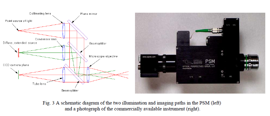
First, if one is going to use a relatively expensive, long working distance (so convex surfaces can be accessed) microscope objective to produce a diffraction limited, focused spot it would be useful if the microscope also imaged as well as a professional reflected light (or metallurgical) microscope. Of course this requires a completely different illumination (Kohler) method than the ASM so this extra illuminator was added to the PSM. However, it was undesirable to have a big, hot bulb hanging off our ASM (along with its big, heavy transformer) so we used red LED’s in the Kohler illuminator and a second beamsplitter to make the PSM a practical, reflected light, imaging microscope as well as shown in Fig. 3 (left).
Another advantage of the solid state illumination is that the whole microscope weighs a fraction of what a reflecting microscope weighs and there is a corresponding reduction in volume. (To be fair the PSM requires an external three axis stage to locate it whereas the stage is an integral part of a reflecting microscope.) Fig. 3 (right) shows a photograph of the PSM with the CCD camera8 on the rear and a Nikon long working distance objective on the front.
A Firewire cable is the power to and video signal from the camera while another cable controls the illumination. The scale of the PSM is obvious from the fiber connector and the Nikon objective and the weight is 600 gm as pictured.
3.2 Additional features of the PSM
Modern microscopes use infinite conjugate objective lenses. The PSM was similarly designed to take advantage of this and add versatility. The use of infinite conjugate optics means that when the objective is removed a collimated beam exits. In this configuration the PSM can be used as an electronic autocollimator.
Speaking of autocollimators, anyone who has used one knows the frustration of getting the light back into the autocollimator aperture and eyepiece. The field of view of an autocollimator that is sensitive to a second of arc has a total capture range of a little more than ±one minute of arc. Often it is necessary to completely darken the lab and then use a flashlight projected into the eyepiece to get a bright enough patch of light back to capture the reflection off the surface under test, particularly if it is an uncoated surface.
The PSM takes care of this problem with a “bright” setting on the laser diode. Slightly less than 1 mW of light comes out the front of the PSM and this is bright enough to see with the room lights on. This makes it easy to find either the return collimated beam, or the focused spot if using the PSM with an objective, under normal lighting conditions. Once even a small fraction of the return light enters the PSM aperture the laser diode can be turned down to the lower setting (which is so dim it is not visible) so the CCD camera is not saturated.
Another feature that makes the PSM very convenient to use is that it is coupled to a computer and that the computer can multi-task. This means that one can take notes of the experiment they are doing while taking data. Settings and video data can be pasted directly into Word or WordPad documents used for tracking experimental conditions. This makes an integrated report that is essentially finished when the experiment is over.
3.3 Simple tests using the PSM
The PSM will do all those tests that one would think an ASM might be good for. We have already mentioned radius of curvature measurement. While the ASM is at the center of curvature of a surface it also measures the optical quality of that surface as in a Star test9. Unless the surface is near perfect, eighth wave or better peak-to-valley, the ASM will show a lack of symmetry in the return spot and the software will give a quantitative analysis of the low order aberrations present. This makes the PSM a good way to do in-coming inspection on optical components for shops that do not have an interferometer.
In an approach similar to measuring the radius of curvature, the PSM can be used as a non-contact way of measuring the center thickness of lenses and windows. For lenses, the curvature of the side being looked through must be taken into account as well as the index of refraction of the material. Then the distance the PSM is moved between the Cat’s eye reflection from the upper surface and the Cat’s eye from the back of the lower surface will give the thickness. This is easily modeled in an optical design program such as Zemax10.
In a similar vein, microscopes are often used to examine surfaces for scratches or other surfaces defects. Yet if a surface is well polished it is very difficult to focus on because it is featureless and has no features with sufficient contrast on which to focus. The PSM solves this problem with the point source because there will always be a Cat’s eye reflection when the PSM is focused on the surface. Once the Cat’s eye reflection is in good focus the sample can be moved laterally until a feature of interest is found because the surface is now in the focal plane of the microscope.
4. APPLICATIONS OF THE POINT SOURCE MICROSCOPE
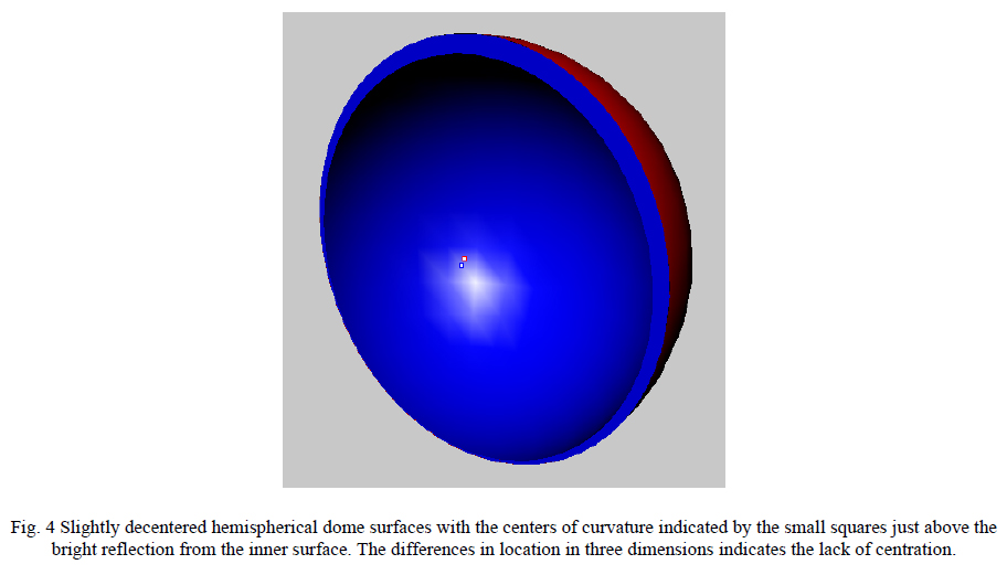
Now that it has been shown what an ASM is and how the addition of a second illumination path and the infinite conjugates optics make the PSM a very versatile and practical ASM, some of the uses of the PSM will be described. The very first example I saw of an ASM at work was at Frank Cooke, Inc. where Ray Boyd used it for checking the concentricity of hemispherical domes. By placing the focus of the ASM at the center of curvature of one surface of the dome a reflection would return from that surface and also from the second surface. Using a filar eyepiece the lateral separation of the two surfaces could be measured. Noting the axial motion of the ASM in focus between the centers of curvature the separation in the axial direction is measured as well as shown in Fig. 4. The apparent separation of the centers of curvature is half the actual separation because of the angular doubling in reflection. It was this simple example that convinced me of the power of the technique of using an ASM.
4.1 Use of the PSM for alignment
Subsequently I have used crude versions of ASMs to align optical systems including off-axis mirrors. The real start of the present PSM was the need to align a catadioptric laser scanning system that included spherical and toroidal lenses and spherical concave and convex mirrors. The centers of curvature of all of the surfaces had to lie on a line that was the optical axis of the system. In this case the PSM was mounted on the ram of a coordinate measuring machine (CMM). The ram was held so the focus of the PSM objective was at the desired height of the optical axis above the CMM table. Using the spacings from the optical design of the system it was then possible to position one lens or mirror after the other so that its center(s) of curvature lay on the optical axis. Use of the PSM reduced the assembly and alignment time of the system from two weeks to one morning and the system aligned using the PSM gave substantially better performance. Other examples of the uses of the PSM for alignment including off-axis aspheres are given in the references2,3.
4.2 Use of the PSM as an electronic autocollimator
A collimated beam of light exits the PSM when the objective lens is removed. When this beam is reflected from a plane mirror at near normal incidence the light returns to the PSM and is focused on the CCD detector by the 100 mm efl tube lens. Since the camera has pixels that are 4.65 μm square and the software centroids to 0.1 pixels the PSM is sensitive to angle changes of 4.65 μradians (0.96 arc seconds) or changes in tilt of the mirror of 2.33 μradians (0.48 arc seconds). Almost all autocollimators read out in the change in angle of the mirror being interrogated rather than the angular change in the light entering the collimator.
Since the detector in the PSM has 1024 pixels in the horizontal direction it has a total range of ±1.4º of mirror tilt and ±1.0º in the vertical. This gives a dynamic range of ±5040:1 in the horizontal. A combination of the sensitivity and total range compare favorably with other commercially available autocollimators, both visual and electronic. Again, because of the packaging, the PSM is a fraction the volume and mass of most autocollimators.
4.3 Use in measuring the centration of plastic molded aspheres
Molded plastic lenses such as those used in cell phone cameras and DVD read heads generally have aspheric surfaces on both sides because the use of aspheres helps eliminate optically active surfaces in a lens design and mold inserts are easily made by diamond turning. The real challenge is to make sure the two sides of the mold line up during the molding process. Misalignment in terms of the decentration and tilt of the two aspheric surfaces will degrade the performance of the lens even though both aspheres have a perfect figure or shape. The PSM is the only instrument we know of that can directly measure the alignment of the aspheric surfaces because it can both image the surface to locate the vertex of the surface and find the center of curvature of that surface to establish the axis of the asphere. The optical axis of the surface is the line joining the vertex and center of curvature of the surface.
4.3.1 Definition of lens centering
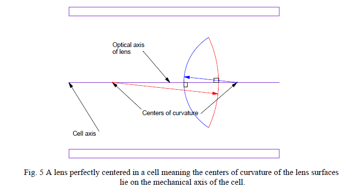
Before demonstrating the process of measurement we must digress a moment to define what alignment means. Whether a lens has spherical or aspheric surfaces the optical axis of the lens is the line joining the centers of curvature of the two surfaces. The lens must be installed in a cell so the lens optical axis is coincident with the axial ray which should also be the axis of the cell. Only in this way does the axial ray strike both lens surfaces at normal incidence and go through the lens undeviated in either displacement or angle. Fig. 5 shows a lens centered in a cell.
4.3.2 The optical axis of an aspheric surface
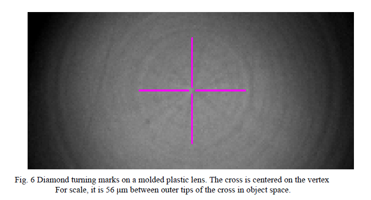
The axis of an aspheric surface is the line joining the vertex and the center of curvature of the surface. On a polished surface there is usually no mark that distinguishes the vertex but on molded plastic lenses the inserts are generally diamond turned and the diamond turning pattern is replicated in the molded lens. This makes it easy to locate the vertex of the surface by imaging on the surface. Fig. 6 shows the diamond turning marks on a precision molded, commercially available acrylic lens listed in the Zemax10 catalog of lens designs.
For a lens with two aspheric surfaces, as is the case for most molded lenses, there are two surface axes and for the lens to be perfectly centered these axes should be coaxial. In this case the optical axis will then be coincident with the two axes of the surfaces. Fig. 7 shows the case of misalignment (left) and perfect alignment (right). Notice that the alignment of the axes of the two surfaces is a part of the lens, or is intrinsic to the lens, and has nothing to do with the centering the lens in a cell, a separate operation.
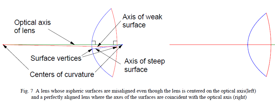
In Fig. 7 the aspheric lens is “centered” as we have defined centering, that is, the optical axis is aligned so an axial ray will strike both surfaces at normal incidence and not be deviated. However, the axes of the two surfaces are not aligned with each other or the optical axis of the lens in the left of Fig. 7. On the right all the axes are coincident and the lens is perfectly aligned, both the surfaces to each other and with the optical axis.
4.3.3 Measurement of the misalignment of the aspheric surfaces
The measurement of the misalignment is quite straightforward. Referring to Fig. 7, the PSM is first focused at the center of curvature of the weak or right-hand surface and the x-y-z coordinates of the center of curvature noted. Then the microscope is focused farther to the right on the surface of the steep or left-hand side of the lens and the xy- z coordinates of the vertex noted. Focusing farther to the right the vertex of the weak side comes into focus as viewed through the steep side and its location noted. Finally the center of curvature of the steep side comes into focus and its location is noted.
Using this set of four x-y-z locations and a spreadsheet, the coordinate system of the points is translated and rotated in two directions until the two points representing the ends of the optical axis of the lens lie along the z axis of the analysis coordinate system with one center of curvature at the origin. This has the effect of putting the center of curvature of each aspheric surface on the z-axis and now it is only necessary to read out the locations of the vertices of the two surfaces in the analysis coordinate system to tell the misalignment. Obviously, if the lens is held in a fixture that locates its mounting surfaces relative to how the lens is held in its cell, the centering of the lens in the cell can also be determined. This whole measurement sequence is easy because the PSM can simultaneously locate both vertices by imaging and the centers of curvature with the autostigmatic feature of the point source.
4.4 A mechanical application – checking a spindle bearing accuracy
By using the PSM and a thoughtfully designed fixture the PSM can be used to measure rotary spindle runout and wobble. The fixture is shown in Fig. 8 (left) and consists of a baseplate that sits on the spindle. On the baseplate are three steel balls that touch each other and form a kinematic support for the two very round (blue) balls separated by a rod. The fixture is slightly easier to use if the balls are magnetized so the rod part of the fixture is more stable.
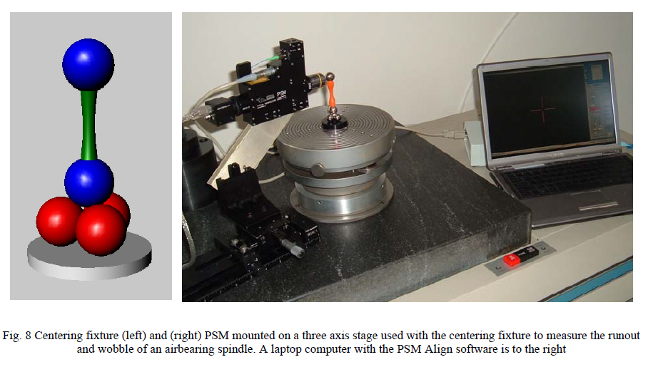
The PSM is focused on the center of the lower ball attached to the rod and as the spindle is turned the ball center will drift horizontally on the PSM laptop display and go in and out of focus. As the baseplate is translated so it is more centered on the spindle axis the drift will be reduced. The best centering is indicated by the minimum displacement of the spot on the display and will have a sensitivity of 50 nm using a 10x objective. Once the lower ball is centered the PSM is moved so it is focused on the center of the upper ball as in the right side of Fig. 8. Now the upper ball can be gently tapped to align the center of the ball with the spindle axis. Because the upper ball pivots about the center of the lower ball the lower ball centering is not disturbed by aligning the upper ball.
By noting the maximum excursions of the centers of the two balls as a function of the spindle rotation the runout and tilt of the spindle axis can be quantified. In addition, vertical motion of either ball indicates axial motion of the spindle. Thus the PSM and a simple fixture can be used to completely specify spindle accuracy to the level of 50 nm in runout and 1 μradian in wobble assuming a fixture ball center spacing of 50 mm.
This measurement could be done as well or better using capacitance gauges but those instruments would be comparable in price to the PSM and the PSM has many other capabilities that the capacitance gauges do not have. Comparable accuracies could also be obtained with air bearing LVDT electronic indicators but the measurement would be more difficult because these are contact devices and might have sufficient force to displace the balls during measurement. Again, costs would be comparable.
5. CONCLUSION
We have described what an autostigmatic microscope is, how it works and why it is a useful optical instrument for aligning and testing optical components and assemblies. We have further described a modern implementation of an ASM with an additional illumination path and greater control over the brightness of illumination that makes the Point Source Microscope a practical, versatile and commercially available adaptation of an ASM. We have illustrated the versatility of the PSM with several examples ranging from an electronic autocollimator to a strictly mechanical application. These are in addition to uses in the alignment and testing of optical systems that have been described in other publications7.
In every application the PSM compares favorably in performance and cost with other specialized optical alignment and test instruments yet because the PSM can do multiple separate functions that it has a value far greater than any one of the separate instruments. In fact, we had one client who claimed he would be hard pressed to think of how he would do certain alignment functions without the aid of a PSM. Also the combination of solid state illumination and small digital CCD camera make the PSM small and light enough to mount on a simple three axis stage so that it may be brought to the optics rather than the other way around. Finally, the PSM Align software produces flexible and quantitative output for residual misalignment and image characteristics at frame rates.
REFERENCES
1. M. Born and E. Wolf, Principles of Optics, 2nd. ed., Macmillan (1964) pp. 149 and 197.
2. R. E. Parks and W. P. Kuhn, “Optical alignment using the Point Source Microscope”, Proc. SPIE, 58770B (2005).
3. R. E. Parks, “Alignment of Optical Systems”, International Optical Design Conference (2006) in publication.
4. T. L. Schmitz, A. Davies, and C. J. Evans, “Uncertainties in interferometric measurements of radius of curvature”, Proc. SPIE, 4451, pp. 432-47, (2001).
5. A. Davies and T. L. Schmitz, “Defining the measurand in radius of curvature measurements”, Proc. SPIE, 5190, pp. 134-45, (2003).
8. http://www.ptgrey.com/products/flea/index.asp
9. W. T. Welford, “Star Tests”, in Optical Shop Testing, D. Malacara, ed., 2nd. Ed., Wiley & Sons, 1992.
10. www.zemax.com