Introduction
- Need for reverse engineering
- Properties necessary for reverse engineering
- How to make necessary measurements
- How to calculate the paraxial properties
- Use of a spreadsheet for the solution
- Use of a lens design program to find a solution
Need for reverse engineering
- Actually want to copy someone’s design
- Concern that lens may be wrong glass
- Lenses got mixed up, need to sort out
- Lens system does not work – right elements?
Properties needed to reverse engineer
- Just looking for paraxial properties
- These are the properties on an optical drawing
- Two radii
- Glass type or index at the measurement wavelength
- Center thickness
- Could measure physically, but may not want to, or can’t
Measurements needed
- Radius of curvature but may not have working distance – reverse lens so backside concave
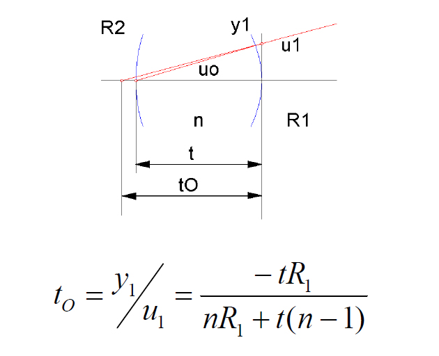
- Optical center thickness to rear vertex
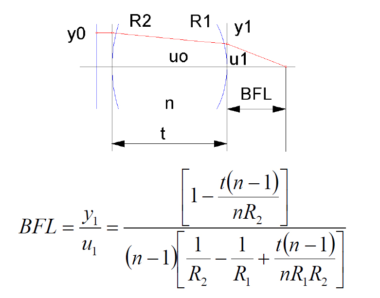
- Back focal length from one or both sides
- Need at least 4 measurements to solve for 4
unknowns - Extra measurements increase confidence
Measurements that can be made
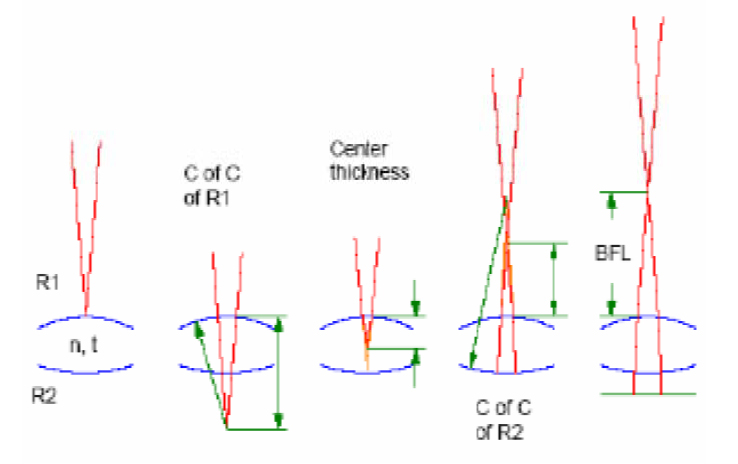
Center thickness
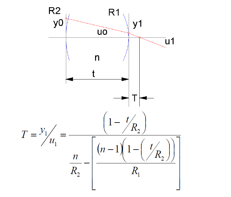
Rear Radius
Back focal length
No closed form solution for unknowns
- Use spreadsheet
- Find difference between measured & guessed values
- Square differences and sum
- Make sum zero by varying unknowns
- Use a lens design program
- Model the various measurement configurations
- Use multi-configuration option
- Use plane surfaces, guess thickness and a model for index
- Use optimizer to find solution
Spreadsheet example
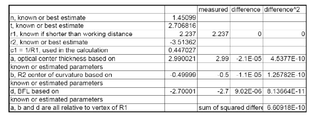
N, t and r2 were estimated and a, b and c calculated
Solver used to minimize lower right hand cell to give calculated n, t and r2 shown above.
Lens design example
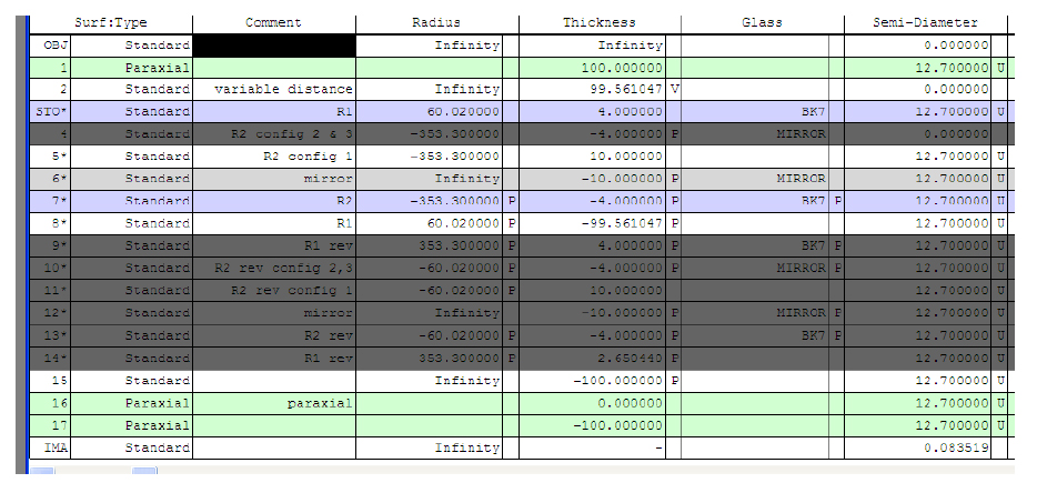
Configuration 1 shown for calculation of bfl
Grayed out lines are ignored
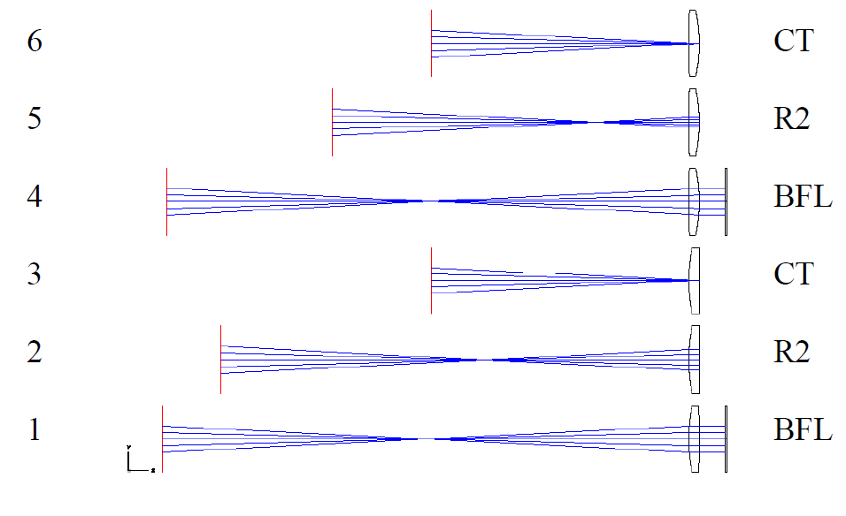
Lens design example con’t 1
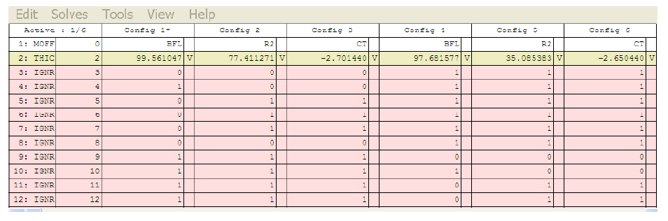
Configurations 1, 2 and 3 are looking thru short radius first
Configurations 4,5 and 6 are looking thru long radius first
Line 2 shows what the measurements should be knowing the index, thickness and two radii
Lens design example con’t 2
Lens design example con’t 3
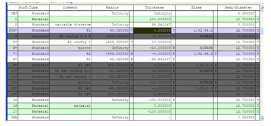
Radii, thickness and index are set as variables
Optimized with small entrance pupil for paraxial solution
Conclusions
- Use all practical conjugate measurements in model
- Works with interferometer or autostigmatic microscope
- Works for doublets as well as singlets
- Can usually see cement interface
- Often better reflection than AR coated surfaces
- Just a more complicated lens design model
- Need to know surfaces from centers of curvature
- Remember to stop down model before optimization
- Model must find first order solution
- All in all, pretty easy to do