ABSTRACT
Traditionally a rotary table is used for optical centering because the table creates an axis as a reference. Previously, we showed that a Bessel beam also creates an axis useful for centering. The Bessel beam axis and a center of curvature of a surface makes it possible to center an optic simultaneously in tilt and decenter. We also showed that simultaneously sampling two arbitrary points along the Bessel beam also permits full adjustment of tilt and decenter of a powered optic. This makes centering possible without either a rotary table or a precision linear stage. In most common instances, however, sampling the beam at two points is unnecessary because of the inability to correct for both tilt and decenter. We discuss an alternative, simpler method using a Bessel beam.
1. INTRODUCTION
Traditionally a rotary table is used for optical centering. When a reflection from a center of curvature is stationary as the table rotates, the center of curvature lies on the rotary table axis. When both centers of curvature of a powered element are stationary as the table rotates, the element is free of both tilt and decenter. To measure this lack of motion requires a precision rotary table and a linear stage to move between the centers of curvature. The actual centering is slow and tedious because you must sample first one and then the other center of curvature, iteratively, to remove tilt at one conjugate and decenter at the other while keeping track of the azimuth of the rotary table so you move efficiently in the proper direction toward sufficiently small motion at both centers of curvature. The process is further complicated because the tilt correction affects the decenter and vice versa. In many cases you have to overshoot the apparent correction at one conjugate to move to centering the other. Needless to say the process begs for simplification.
Previously we showed that using a Bessel beam1 as reference axis would eliminate the need for a rotary table for centering2. This means simple x-y motions of the element being centered are guided by reflected spot movements on a video screen. This directly couples alignment motions of the element in a particular direction with visual feedback from a video screen showing complementary motions in the same azimuthal direction making for efficient and intuitive hand/eye coordination. By sensing the position of the Bessel beam and a reflection from the center of curvature of the element in the same plane, the optical axis of the element is defined by a point and two angles. Overlapping the two spots on the axis of previously aligned crosshairs guarantees the optical axis of the element lies on the Bessel beam reference axis. Using this method, a powered optical element can be fully centered in tilt and decenter quickly and without iteration.
However, the method is not entirely free of error. If the initial element in an assembly is not perfectly aligned in tilt and decenter the Bessel beam transmitted through the element will no longer be perfectly aligned with the reference Bessel beam before the first element was installed. This will lead to small errors in the centering of subsequent elements. This is not to say that equivalent errors also occur using a rotary table, but for best practice the method should eliminate or minimize these errors. Another short coming of this method is that for elements with centers of curvature close to the element, the sensor must be close to the element and that interferes with access to the element for centering, cementing and cleaning. What would be ideal would be a method where the sensor was positioned relatively far from the element being centered.
In an attempt to overcome these deficiencies we first came up with a method that uses the benefits already described, but uses them in a way so that the sensor is a sizable distance from the elements being centered. Further, the sensor is fixed at that distance for the entire centering process of one or more elements. In this method3, an optical trombone is placed between the lens being centered and the sensor so the Bessel beam can be sampled at two axially separated points. By sampling the beam at two separated points the displacement as well as the angle of the beam are determined giving enough information to completely center a lens both in tilt and decenter.
The method worked well and just as expected, but as we used the method to center lenses we realized the approach was overkill in the sense that in most cases of centering there is no means of adjusting the lens in both tilt and decenter. This new method gave more information than was useful in practice.
The other feature of the method was that in sampling just one point along the Bessel beam the method was quite sensitive to errors in centration. Because the sensor could be placed relatively far from the lens being centered there was a substantial optical lever arm that made the method sensitive. Thus for practical reasons, and the idea that simpler is better, we decided not to use the optical trombone, but to use a single point of reference on the Bessel beam to determine best centering.
In this paper we describe why a majority of lenses can only be centered in either tilt or decenter. Certainly there are very high quality lenses where there are sufficient adjustments to achieve centering in both degrees of freedom, but we limit our present discussion to the majority of lenses in consumer products where a lens can only be centered in one degree of freedom.
We show the theory of centering in one or the other degrees of freedom in terms of their sensitivity to centering errors in terms of first order optical lens parameters. Then we show the calculated sensitivities match those predicted by the theory.
2. PRACTICAL CONSTRAINTS TO CENTERING
Most lens cells have a seat and a bore nominally centered on the axis of the cell as shown in Fig. 1a. Also, most assembly takes place using gravity to hold the lens down to the seat. This is why we do not consider the case where the seat is above the lens. In Fig. 1b we show a plano-convex lens sitting on the seat. This lens can always be perfectly centered to the cell by sliding the lens on the seat independent of how well the lens optical axis is concentric with its edge (up to the point that the periphery of the lens hits the side of the cell).
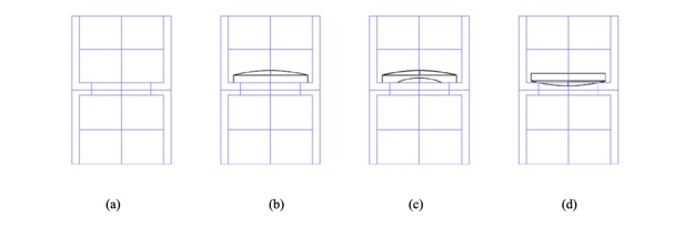
Fig. 1 A typical lens cell with seat and bore (a), a plano-convex lens sitting on the plane seat (b), a meniscus lens with an edged flat sitting on a plane seat (c) and a spherical surface sitting on the bore in the seat (d)
On the other hand it is clearly impossible to tilt this lens provided the seat is perpendicular to the axis of the cell. In Fig. 1c we have much the same situation, but here the flat on the lens resting on the seat was added by edging and an error in tilt could be introduced during edging. As with case 1b, the lens can only be adjusted by translation but how well it can be centered depends on how well the flat on the lens is perpendicular to the axis of the lens. The difference in cases 1b and 1c, relative to centering, are that edging tolerances matter in the case of 1c but can be loose for 1b up to the point of mechanical interference with the cell.
In Fig. 1d, the lens, whether it is plano- or bi-convex, can be centered perfectly by tilting alone as long as the bore in the seat is perfectly centered to the cell. If the bore is centered and the seat perpendicular to the cell axis, the lens rotates about the center of curvature of the surface resting on the seat. That means the center of curvature necessarily lies on the axis of the cell. As the lens is rotated about the center of curvature of the surface on the seat, the center of curvature of the opposite face can always be brought onto the axis of the seat, again as long as the edge of the lens does not hit the cell wall.
A ray of light coming from under the lens and centered on the cell axis will not be deviated by the lower surface because it hits the surface at normal incidence. When the lens is rotated in the seat until the center of curvature of the upper surface also lies on the axis of the cell, the ray strikes the upper surface at normal incidence and is undeviated. Again, edging tolerances can be loose as long as there is clearance to center the lens by tilting about the bore in the seat. In this scheme the tight tolerances are placed on the cell and getting it well aligned to the centering fixture.
3. SENSITIVITIES TO ALIGNMENT
3.1 Plano surface on the seat
Assume that the cell is made perfectly and is aligned perfectly to a centering fixture such that the cell mechanical axis is coincident with a Bessel beam projected from under the lens. Light from infinity parallel to the cell axis would come to focus at the back focus of the lens in Fig. 1b. If the lens is centered on the Bessel beam the beam will also pass through the back focus4. If the lens is slid a distance, d, to the right, the back focus will move d to the right and the Bessel beam will deviate so that it also passes through the shifted back focus. This means the deviation of the Bessel beam is just
α = d/efl, (1
where efl is the effective focal length of the lens.
With a collimated beam of light this shift of the back focus can only be sensed in the plane of the back focus. With a Bessel beam, the position of the beam can be sensed at almost any distance from the lens except in the vicinity of the back focus because there the beam expands to an annulus. If the lens has an efl of 10 mm but the viewing microscope is 100 mm from the lens, a 1 μm decenter of the lens will be seen as a 10 μm motion of the spot in the microscope. The angular deviation of the Bessel beam behaves as d/efl for any power of lens, positive or negative, the only difference being which way the Bessel beam moves relative to the lens axis.
3.2 Spherical surface on the seat
If a spherical surface sits on the seat as is the case in Fig. 1d the only means of centering the lens is to rotate it about the center of curvature of the surface on the seat. Calculating the deviation of the beam is a bit more complicated than in the case of decenter. Consider Fig. 2 with a bi-convex element tilted by an angle α. The center of curvature of R2 then lies a distance
h = (R1 – R2 – t)sin(α) (2
from the axis of the cell. This means the normal, β, to R2 is h/R2 and after refraction at R2 the deviation of the beam deviation is
γ = [(n – 1)(R1 – R2 – t)sin(α)]/R2 (3
Equation (3) says the deviation is directly proportional to the lens tilt, α, and to a term related to the shape factor of the lens in the sense that as long as [(n – 1)(R1 – R2 + t)/R2] remains constant, the deviation is independent of the lens focal length.
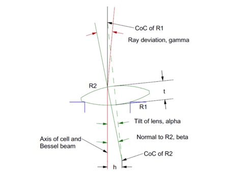
Fig. 2 The ray deviation of a tilted lens with a convex surface on a centered seat
For example, as the surfaces become more concentric, the angular deviation goes to zero. For a plano convex lens as in Fig. 1d, the deviation is α/2 independent of the efl while for an equi-convex lens the deviation approximately α independent of the efl. Just as in the case of decenter, the deviation may be measured at almost any distance from the lens except in the vicinity of the back focus so that there is good sensitivity to the deviation of the Bessel beam.
There are practical limitations to how far the sensor can be from the lens. As the sensor is backed away from the lens the Bessel beam becomes less intense and the sensor views a larger area of scattered light so there is a decrease in signal to noise at large distances. However, the use of the Bessel beam makes possible a situation that is impossible with conventional imaging, the ability to view the propagation of a single ray at almost any axial distance. This is what makes the use of the Bessel beam so powerful and lets you move the sensor well above the cell so there is space near the cell to work and inspect the assembly.
4. EXPERIMENTAL VALIDATION OF CENTERING SENSITIVITIES
4.1 Case of decentration only
In order to test the simulation in Section 3 we used a catalog lens, nominally a 200 mm efl plano-convex lens. The seat for the lens, shown in Fig 3a, was on an x-y stage so we could center the seat to a Bessel beam projected from under the seat. In Fig. 3b we used a ball and a Point Source Microscope (PSM)5 focused at the center of the ball to center the seat to the Bessel beam. The first step to center the ball was to determine the height of the ball center with the ball on the seat and set the PSM to that height. Then the ball was removed and the PSM was translated perpendicularly to the Bessel beam coming up from under the seat so that the crosshairs in the PSM were centered on the Bessel beam. Then the ball was replaced and the x-y stage with the seat was moved to center the ball on the PSM crosshairs.
Fig. 3c shows the lens sitting on the seat convex side up and the microscope focused substantially about the lens. The first set of tests were made with the plano side on the seat as in Fig. 3c so the angular deviation of the beam should be strictly proportional to the lens efl.
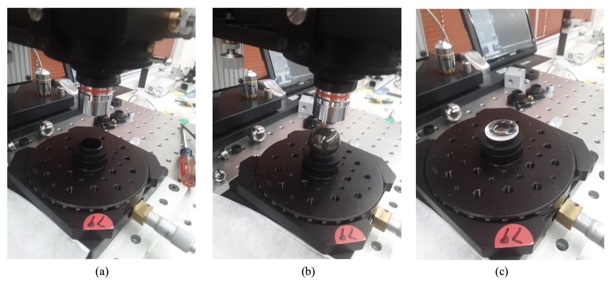
Fig. 3 The lens seat (a), the lens seat being centered using a ball (b) and the plano side of the lens on the seat (c)
The first measurement was made with the PSM focused on the vertex of the convex surface with the lens closely centered with respect to the Bessel beam. The second measurement was made after decentering the lens by 1000 μm. The cropped images from the PSM video screen are shown in Fig. 4 where the tick marks on the red bar are 100 μm apart. Using the centroiding algorithm in the PSM it showed the spot moved about 8 μm right to left for a lens decenter of 1 mm in the x direction while a Zemax simulation of this case showed the spot should have moved 2 μm.
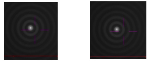
Fig. 4 Cropped images of the Bessel beam with the PSM focused at the vertex of the convex side of the lens. On the left is the beam position prior to decentering. On the right is the position after decentering 1 mm. The spot moved 8 μm
One might ask why did the spot move so little for a 1 mm decenter of the lens until you realize that when you are focused at the vertex of the lens you are only 0.4 mm above the 2nd principle plane, in this case, where there should be no motion of the spot. The second thing to realize is that if you can focus on the vertex and see the Bessel beam, you can also focus on the principle plane and see there is no motion in this plane. This means you can make a precision measurement of the efl rather than the bfl of any lens without the need for a nodal slide.
Next, the PSM was moved up to 100 mm above the vertex where the lens was again centered with respect to the Bessel beam and then decentered 1000 μm. This time the spot moved 488 μm and Zemax predicted a motion of 500 μm. Fig. 5 shows the spot motion. Because the motion was large we decentered the PSM to move the spot to the right initially so that the spot remained on the screen when it was decentered. Also, we had to leave the picture full size in the direction of the decenter for a comparison between the two situations. The PSM centroiding algorithm was used to measure the spot location before and after decentering.
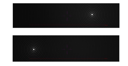
Fig. 5 Bessel beam spot locations 100 mm above the lens centered (upper) and decentered by 1 mm (lower) showing a movement of 488 μm. Red tick marks 100 μm apart
Moving up to 200 mm above the vertex, the decenter was reduced to 500 μm so the spots would not go off the screen. In this case the spots moved 491 μm while Zemax predicted 499 μm. If the spot motion is plotted against distance from the lens the slope of this line in 0.00487 where Zemax predicts a Bessel beam deviation of 0.00498. Above 200 mm the Bessel beam spot disappears because you are in the region of the back focus. Once you get above this region for this longer focal length lens the Bessel beam spot lacks intensity to make a good measurement. On the other hand if a 500 μm decenter shifts the beam approximately 500 μm and you can measure the beam to a 1 μm sensitivity you have a sensitivity to decenter of about 1 μm. In angular terms this as about 1 second of arc, that is, 0.001/200 mm = 5 μradians ~ 1 second.
To recap, for decenter, the angular beam deviation is just the decenter over the efl and the spot motion is the deviation times the distance above the lens the measurements is made. If the measurement distance is close to but less than the bfl, the Bessel spot displacement is very close in magnitude to the amount of the decenter.
4.2 Case of lens tilt only
The other case is tilt of the lens when the powered side of the lens sits on the seat. With the equipment at hand it was difficult to directly measure the tilt of the lens in the seat. The experiment was modified so that we decentered the lens and modeled what that decenter did to the angular beam deviation using Zemax. For a 50 μm decenter of our 200 mm efl lens, Zemax predicted the beam deviation was 0.02354°, 1.41 arc minutes or 411 μradians. For the constant 50 μm decenter the spot position was measured every 50 mm above the lens.
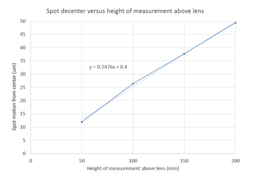
Fig 6 Bessel beam shift as a function of distance above the 200 mm efl lens
Again the measurement can be taken at any convenient height above the lens as long as it is not close to a back focus. Since the decenter we used was equivalent to a lens tilt of 411 μradians and the spot moves about 50 μm when measured 200 mm above the lens we have a measurement sensitivity of about 8 μradians to tilt for this lens assuming a 1 μm sensitivity to spot displacement, far better than needed for all but the most precision lenses. In addition, if we look back at the equation for the beam deviation for this lens we find the deviation γ = 0.585α and our α = 411 μradians so γ is 240 μradians, almost the same as the slope of the graph in Fig. 6 taking into account the slope is shown in units of μm/mm.
5. CONCLUSION
Once we realize that for most centering there is a single degree of freedom, either tilt or decenter, the whole problem of centering is vastly simplified if we also take advantage of the property of Bessel beams to propagate as though they were a single paraxial ray. Then the beam deviation or decentration can be measured at almost any practical distance above a lens or lens assembly without ever having to move the measurement device. Further, whether the centering error is tilt or decenter, either can be measured on the order of 1 μm or 1 second of arc if you have the ability to measure the Bessel beam position to 1 μm. This ceases to be true for very short focal length lenses but one can always use a higher power objective to give greater sensitivity to spot motion.
It has already been noted that centering without the need for a rotary table was 5-6 times as fast as using the rotary table6. The drawback to the method proposed there was that the vertical column on the centering device either had to be very good, or very well calibrated. By using a Bessel beam that propagates like a single paraxial ray there is no need for the precise column. The sensing unit is put at a convenient height and never moved throughout the centering process. As always in the case of optics, one size never fits all, but almost all cases can be covered with this method.
REFERENCES
[1] Durnin, J., “Exact solutions for nondiffracting beams. I. The scalar theory”, JOSA-A, 4, 651-4 (1987).
[2] Parks, R., “Alignment using plane Axicon gratings”, Proc. SPIE, 10747, 1074703 (2018)
[3] Parks, R., “Practical considerations for using grating produced Bessel beams for alignment purposes”, Proc. SPIE, 11816, 1181603 (2021)
[4] Parks, R., “Design for alignment”, Proc. SPIE, 11103, 1110302 (2019)
[5] https://optiper.com/en/products/item/point-source-microscope
[6] Heinisch, J., Hahne,. and Langehanenberg, P., “Rotation-free Centration Measurement for Fast and Flexible Inspection of Optical Lens Systems”, Proc. SPIE, 11175, 111751B (2019)