1. INTRODUCTION
It is common to think of computer generated holograms (CGH) as artifacts for testing aspheres but they can also be used as general calibration artifacts and fixtures for the alignment and test other more conventional optics. We show how simple Fresnel zone patterns can be created to simulate centers of curvature or axes in space with dimensional precision associated with microlithography. These centers of curvature and axes can then be located in space to similar sorts of precision with an autostigmatic microscope (ASM) or an interferometer.
Once the ASM is centered on the center of curvature, or axis, of the Fresnal zone pattern, a ball, or cylinder, respectively, of matching radius can be aligned to the ASM or interferometer to similar sorts of precision and physically attached to the CGH to serve as kinematic datums against or on which to mount other optical or mechanical components.
We then give an example of the fixture for the mounting of a rectangular lens element into a kinematically located frame so the two can be cemented together prior to inserting the bonded pair into an optical bench.
2. ORIGIN OF THE CONCEPT
From their earliest use as null devices for testing aspheres, CGH’s had to be precisely aligned to the interferometer used for the testing. This was originally done by attaching balls to the corners of the CGH’s using the mechanical features of the CGH’s as datums. More recently, Coyle [1] showed that the balls used for alignment could be attached to the CGH in a more precise way, and more importantly, one that was directly related to the aspheric test pattern by including in the overall CGH pattern, Fresnel zone patterns that defined the locations of the centers of the alignment balls.
While Coyle originated the idea of locating datum balls on CGH’s, she used a purpose built autocollimator with a monochromatic light source. The balls can be located just as easily and precisely with a commercially available ASM, or with an interferometer for even higher precision.
3. SECURE MOUNTING OF THE BALLS
In the original implementation of adding datum balls to CGH’s they were cemented directly to the CGH. The actual mechanical connection of a steel ball to a glass plate with an adhesive such as epoxy is problematic in two respects; the joint with the ball standing proud of the plate is highly susceptible to a lateral blow, and if the blow is sufficient to knock the ball loose there is a high likelihood of the cement pulling out a piece of the glass due to the nature of the bond.
We feel a better means of fastening the balls to the CGH is via the nests used for the SMR’s used in conjunction with laser trackers. The Fresnel zone pattern is adjusted in radius to compensate for the thickness of the nest and the ball/nest pair is used to locate the nest which is then cemented around it periphery. The lower profile of the nest makes it less vulnerable to getting a sideward blow and the greater area of the cemented joint makes it less likely the nest will be knocked off the CGH. Of course, in the worst in instance of the bond being broken the damage to the CGH would probably be greater.
4. EXAMPLE OF A FIXTURE FOR MOUNTING AN “OFF-AXIS” LENS
In this example it was required to align a rectangular meniscus lens element to its kinematically located mount so the two could be cemented together. The rectangular lens was cut out of the meniscus so the optical axis of the lens lay outside the lens as shown in the Fig. 1.The mount was designed with pins so that once the lens was aligned and cemented to the mount, the cemented pair could be deterministically located on an optical bench via the pins.
A CGH is laid out with a Fresnel zone pattern to focus light at the center of curvature of the concave side of the meniscus with allowance for the lens thickness and diameter of the balls. In addition, three balls are positioned relative to the Fresnel pattern to locate the center of curvature of the convex side to define the other end of the optical axis of the lens. When the lens is placed on the three balls, the center of curvature of the convex side will lie on the optical axis of the lens as defined by the position Fresnel pattern on the CGH and the center of curvature of the concave side it creates.
When an ASM is focused on the center of curvature of the concave side produced by the pattern, the lens is slid on the 3 balls until its center of curvature is centered in the ASM aligning the lens to the fixture. A metal fixture plate drilled to accept the pins on the mount is located on the CGH by 6 additional balls, 3 to determine a plane parallel to the CGH and of the correct height. Three other balls locate the plate in 2 degrees of translational freedom and one of rotation so that when the lens mount is mated with the plate, the mount is in the correct position relative to the lens as shown in Fig. 2. From a drawing of the plate and mount, Fresnel patterns are printed on the CGH for the 6 balls locating the fixture plate. Obviously the entire pattern is printed on the CGH at one time with the locations of the Fresnel patterns located to microlithographic precision.
5. OTHER ASPECTS OF CGH FIXTURES
Two other properties of the CGH’s used as fixtures should be mentioned. The first, pointed out by Coyle is that at each Fresnel location, centers of curvature are created on each side of the CGH so that these two centers of curvature establish an axis without having to autocollimate off the CGH, if this is useful during alignment. The other thing is that a pattern of equally spaced rings can be used to create an axis perpendicular to both sides of the CGH that extends indefinitely provided there is sufficient intensity in the focused point source of the ASM used to locate the axis. The equally spaced rings create an axicon that in turn creates a conical wavefront. The only disadvantage of this use of the CGH is that the efficiency of the pattern decreases with distance and the intensity of the point source must be increased with distance.
6. CONCLUSION
We have given an example of how a CGH may be used as a fixture for the alignment of optical and mechanical components when used in conjunction with an ASM to interrogate the CGH. We believe we have explained the method in sufficient detail that many other examples can be readily imagined. As another example, entire symmetric optical systems can be precisely aligned without the need for a rotary table; the axicon CGH creates the reference axis in space.
7. REFERENCES
[1] L. Coyle, “Precision Alignment and Calibration of Optical Systems Using Computer Generated Holograms”, Ph.D. dissertation, Univ. of Arizona (2014), https://hdl.handle.net/10150/332847.
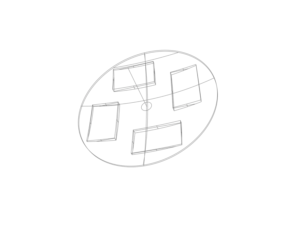
Fig. 1 Menicus lens showing the “off-axis” rectangular lenses positioned relative to the axis of symmetry of the meniscus.
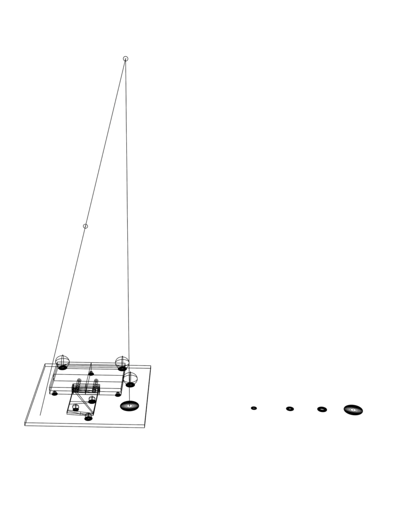
Fig. 2 CGH as a fixture for alignment of a rectangular lens relative to a mount designed to be pinned to an optical bench