As I said in the first chapter, I hope to make these articles into a book on alignment after significant editing to organize the material coherently. In that spirit, and before I forget, let me discuss some aspects of alignment and precision engineering that belong in a Preface or Introduction to the book rather than here. My motivation is returning from a meeting of the American Society for Precision Engineering, where I took a tutorial on alignment from Vivek Badami of Zygo and Eric Buice from Lawrence Berkeley National Laboratory. You might ask why since I am writing on this subject, but everyone views alignment from a different perspective, and there are aspects of the subject that you might never have thought of but are essential to others. For example, Eric is interested in the alignment of magnets in an accelerator using a wire as the detector of the axis of the magnetic field.
From the alignment tutorial and papers at the meeting, a couple of principles of precision engineering stand out. How well you can make measurements depends on the environment you are working in. At least three significant causes of disturbance exist: thermal effects, vibration, and air turbulence. To give concrete examples, I have attached a paper written several years ago about a large machine tool that illustrates these effects nicely. For each category, I refer to the illustration in the paper. For the details, please see the paper itself.
Thermal effects cause dimensional changes in most materials, and at the µm level and below, people worry about temperature changes of millidegrees. These dimensional changes cause drift and a lack of repeatability. The first example in the paper deals with the lights in the room where the machine was installed. Being conservation-minded folks, we turned the light off in the evening and back on when we got to work in the morning. Unfortunately, this caused an 18 µm change between the tool and workpiece and took most of the workday to stabilize. We just left the lights on all the time, as in Figure 3.
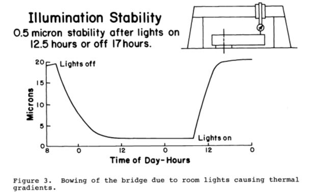
Figure 4 in the paper shows that 0.1° F. change in room temperature will cause a damped reduced temperature of the steel in the machine. The nominal control of the room temperature to 0.02° for several hours was enough to make this a minor contributor to machine errors.
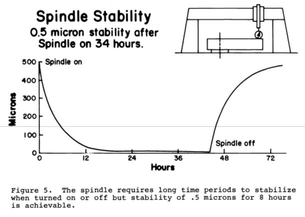
The biggest thermal effect was running the machine spindle. It elongated by 0.5 mm over a 20-hour period. Again, leaving the spindle running except for changing wheels was the only solution, as in Fig 5. In general, thermal effects are categorized as systematic effects; they are relatively long-term effects compared to the time needed to correct for the effect by some feedback mechanism.
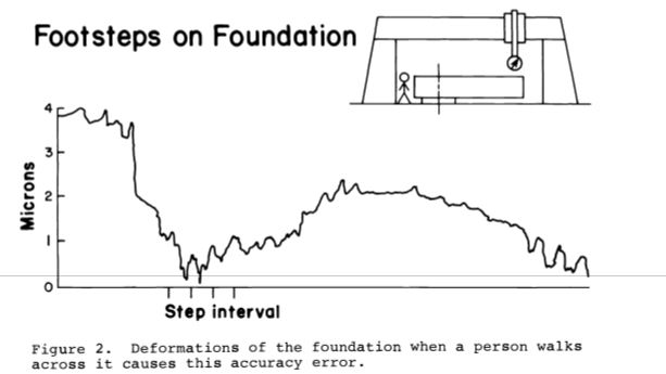
In the vibration category, we usually think of seismic vibration coming up through the floor and forget about acoustic vibration. However, even when taking precautions, as shown in Fig. 2, it pays to stay off isolated foundations and avoid touching isolated optical tables during experiments. Leave your laptop off the table and as far away from the experiment as possible. It is a source of vibration and thermal effects.
Acoustic vibrations also have consequences. While I can’t document this, I remember watching a part being diamond-turned at Oak Ridge National Laboratory. They had a claxon to signal for an incoming phone call. You could see the change in the part’s surface finish from several feet away when the claxon sounded. In another case, having flooring too near the underside of an isolated optical table is a problem. Walking on the floor transfers deflections in the floor to the table because the air between couples the flooring to the table. Here I speak from experience. Opening the gap a couple of inches fixed the problem. The effect of both kinds of vibration combines systematic and statistical noise. Sometimes isolating your experiment from the environment is easy, but just when you think you have it isolated, another source of vibration pops up.
Anyone who has used an interferometer is aware of air turbulence. The irregular change in the shape of the fringes is a sure sign of turbulence. It is also visible in the image using an autostigmatic microscope (ASM). The image’s centroid will dance around, and the flair around the edges of a well-focused spot will change. This type of noise is largely statistical, and the practical method of reducing statistical noise is through averaging. One area of precision engineering that has made large steps here is the astronomical community, which combines wavefront sensing and deformable correction optics to improve the images of stars and galaxies dramatically.
This thought brings me to another impediment to precision, at the µm level, everything is deformable, and to first order, all materials should be considered rubber. Fig. 6 in the paper is a beautiful example.
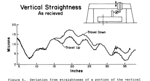
The ways along which the tool spindle moved were ground steel blocks with a cross-section of 50 by 150 mm. As the spindle moved past the bolts that held the ways together, there was a roughly 10 µm bulge every 150 mm due to over-tightened bolts. Loosening the bolts largely corrected this straightness error. Since the stiffness of plates varies as the thickness cubed, it is easy to see why the least stress will distort thin plates such as lenses and mirrors.
This is probably enough on the difficulty of doing precision work, but it leads to a topic I want to discuss in the next chapter, once you have aligned a system, how do you secure the alignment? The tutorial I attended had a good discussion of this topic, and I will share some of their thoughts in the next installment.