ABSTRACT
Bessel beams are useful for alignment because they create a small diameter, bright, straight line image in space perpendicular to the Axicon, or Axicon grating, producing the beam that is an exact analog of a single ray in a ray tracing program. Here we limit our discussion to Bessel beams produced by plane gratings whose pattern is evenly spaced concentric circles that are illuminated by a point source of light on the grating axis. The gratings produce a more nearly ideal Bessel beam than a lens type Axicon, and the plane grating serves as a plane mirror as well in an alignment setup so the combination define four degrees of freedom in space rather than the usual two.
Most discussions of Bessel beams assume illumination with collimated light. We have found it advantageous to use a point source for illumination because it is easy and less expensive to use a single mode fiber as a source than a precision collimating lens the diameter of the Axicon. Besides, collimated illumination produces a Bessel beam of finite length in transmission while in theory a beam of infinite length is created using a point source.
With these assumptions about how the beams are produced and details about the grating diameter and line spacing it is easy to calculate the useful length of the Bessel beam in reflection from the grating, the usual matter of concern when using the grating for alignment purposes in a double pass test setup. Other practical matters are also discussed such as lens centering with a test apparatus with no moving parts.
1. INTRODUCTION
Credit for the discovery of Bessel beams generally goes to back to Durnin1 in 1987, but really the credit should go to McLeod2 in 1954 where he describes the invention of the Axicon because the beam created by an Axicon is a Bessel beam. Unfortunately for McLeod he did not have a laser at his disposal and so the bright spot created by his Axicon did not show much (any) of the structure surrounding the bright spot and he did not realize he had stumbled on this new form of light beam. Besides, McLeod was a very practical person primarily interested in alignment of optical systems, not the physics of the beam produced by the Axicon3.
Even after McLeod wrote a second paper4 describing uses of the Axicon for alignment there was not much interest in Axicons until Durnin’s1 sparked an interest because of the so-called non-diffracting nature of Bessel beams. Also, Durnin and his coworkers were initially creating their Bessel beams not with Axicons, but rather with opaque screens with a narrow annulus that created the Bessel beam on the axis of the annulus. This led Vasara5 to realize Bessel beams could be created by plane gratings, in part, to make the beam more efficient in terms of light through put by using the full aperture instead of just an annulus.
In spite of several papers6,7,8 including the widely distributed Optics & Photonic News9 mentioning uses of Bessel beams for alignment, virtually all the interest in Bessel beams has been in other areas of optics, astronomy and physics. There seems to be almost no interest in this simple yet powerful technique for the practical, everyday alignment uses such as cementing doublets and centering optics in a barrel, let alone aligning optics in 2 and 3 dimensional space where alignment becomes more of a challenge particularly if it has to be done precisely. The purpose of this paper is to attempt to illustrate some of the practical concerns of using Bessel beams so it is easier for others to take advantage of this powerful alignment technique.
2. WHAT IS A BESSEL BEAM AND HOW IS IT PRODUCED?
Before getting into the practical issues of using Bessel beams it makes sense to review what Bessel beams are and how to produce them. Referring to Fig. 1, a plane wavefront is incident on a narrow annular aperture centered on and at the back focus of a lens.
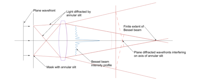
Fig. 1 Creating a Bessel beam using a plane wavefront and an annular slit at the back focus of a lens (after14)
This is how Durnin, et. al. 1 created their Bessel beams. In the plane of the page, the lens collimates the light from the upper portion of the slit to produce a plane wavefront progressing downward from the lens that has a width of the slit diameter, while the lower portion produces a plane wavefront of the same width progressing upward. Since the picture is symmetric about the axis of the annulus and lens, these two wavefronts produce a set of nested cones of light in the region where the wavefront overlap.
The phase of the light at the apexes of the nested cones interferes constructively along the axis creating a line of light whose intensity is much greater than in the region surrounding the axis. This bright line is the core of the Bessel beam and is the useful portion for centering. The intensity of the light in the core along the axis varies in an oscillatory manner and gets less intense near the lens but never goes to zero as shown in Fig. 2a. Perpendicular to the axis the light also varies in rings of diminishing intensity away from the bright core as shown in Fig. 2b.
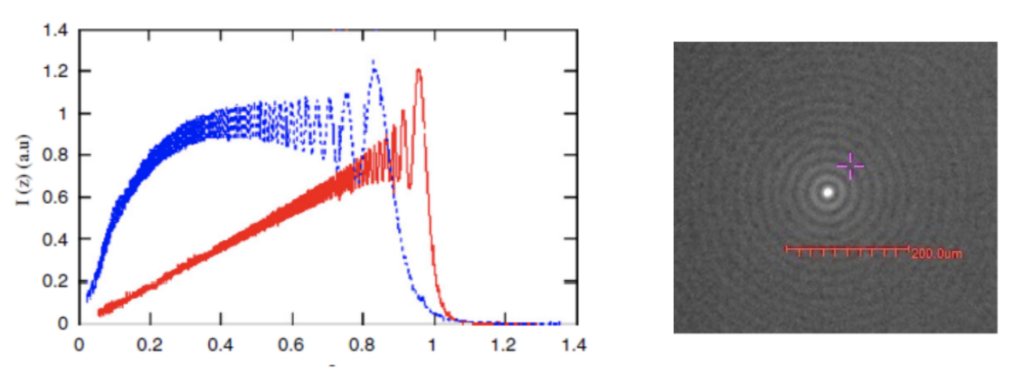
Fig. 2a Variation in intensity of the Bessel core in the direction of propagation for a plane wavefront (red) and converging wavefront (blue) (left ) from reference 11 and Fig. 2b variation in intensity perpendicular to the axis of the beam (right)
From a practical standpoint, the Durnin method of using an annulus is inefficient because most of the aperture of the lens is obscured. A physical, cone shaped glass Axicon as McLeod used also creates a Bessel that uses all the light incident on the clear aperture of the Axicon. Fig. 3 illustrates how the Axicon creates a nested set of cones of light although only one is shown because making a figure with many cones is difficult. For each different ray height of the spherical wavefront impinging on the Axicon a different diameter ring of virtual sources is created that cross the axis of the Axicon at a different distance from the tip.
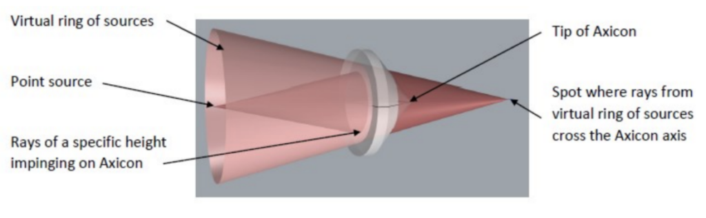
Fig. 3 Illustration of how a conical Axicon creates the nested cones of light to form a Bessel beam
A third way of creating a Bessel beam is to use a pattern of equally spaced, concentric rings printed on a photomask substrate, in other words, a computer generated hologram (CGH)5. This can be pictured similarly to Durnin’s approach but no lens is needed. Looking at the pattern of circles edge on with the center of the pattern in the plane of the page, the pattern acts like a linear diffraction grating to an incident plane wave. A small amount of light goes straight through the grating as the 0 order while much of the rest of the light is diffracted into + and – first orders at an angle of λ/d where λ is the wavelength of the incident light and d is the pattern line spacing. Now the nested cones are made up of the + 1st order light as the page is rotated 360 degrees around the axis of the pattern.
Roughly 40% of the incident light goes into the transmitted Bessel beam for a binary grating pattern and 40% into the reflected beam. While this is less efficient light wise than a physical Axicon, the CGH has 2 distinct advantages over the glass Axicon. First, the CGH is also a plane mirror and therefore simultaneously defines 5 degrees of freedom, 3 translations and 2 angles, a great advantage to anyone doing alignment. The second advantage over the cone shaped Axicon is that the grating pattern is almost perfect in the sense that CGHs can be written with an rms precision on the order of 1 part per million or better10 over a scale of spatial wavelengths of at least 10^4.
There are two questions that may be asked about the precision, what about wavelength of illumination and the flatness of the substrate. First, the Axicon gratings work at any wavelength. You can create a Bessel beam with white light. Regarding substrate flatness, it is hard to imagine a low order deformation that will affect the straightness of the Bessel beam. Power and astigmatism may affect the shape of the rings around the core but it would have to be an error like the “S” shape of coma before the straightness of the beam would be affected, and this high an order of deformation is difficult to induce mechanically.
A final comment of the relative advantages of a conical glass Axicon versus a grating. At the present time a physical Axicon 25 mm diameter is less expensive than a similar size grating in unit quantities by perhaps a factor of 2. In some cases they are essentially the same price. Because the grating Axicons can be produced by contact printing the price will become much less expensive with higher volumes. Since Axicon gratings are “perfect” and more flexible to use than true conical Axicons the balance of the discussion will be limited to grating Axicons.
3. DESIGN AND USE OF AXICON GRATINGS
When Axicons are discussed the immediate mental picture is that they are illuminated with a collimated light source. Most of the literature assumes this because it is a little easier to describe the theory. However, use with a collimated source limits the scope of use and the ease of implementation. First, a good lens the same diameter as the Axicon is needed to collimate the incident light. Second, the collimated input limits the theoretical length of the transmitted Bessel beam. Using a point source of light a known finite distance from the grating permits a Bessel beam in transmission of almost any length. Because any Axicon makes relatively inefficient use of the light incident on it, a laser source is almost a necessity in practice to produce a long Bessel beam.
An adjustable 1 to 10 mW laser diode source coupled into a single mode fiber makes an ideal source with which to illuminate the grating via a free space coupling. Such a fiber patch cord in the visible will have a near perfect Gaussian output with a NA of about 0.1. This source placed about 125 mm behind a 25 mm diameter grating gives about optimum coupling to the grating, at least for illumination purposes. This convenient set of initial parameters will be used now to examine the Bessel beams produced by these constraints. It will be obvious how to deviate from these values depending on the specific situation.
A next obvious question is the line spacing of the pattern. I made a reasoned guess at 10 μm lines and spaces to give a grating spacing of 20 μm. Using this spacing with 635 nm light gives λ/d = 0.03175 = 1.815° = α. It has turned out that this was a good choice. Gratings with this spacing are easy to make and the diffraction angle seems to be useful for all applications I have tried so far. This is not to say there will not be a case where another spacing is a better choice but I cannot see anything wrong with this choice, at least as a good place to start.
3.1 Properties of the Bessel beam in reflection
Because the grating line pair spacing of 20 μm has worked out well it will be used for further discussion. Also, it has been convenient to size the grating at a 25 mm diameter so we’ll use that as well in the example but a practical upper limit would be 140 mm for a 6 x 6” photomask substrate. If we put a point source of light a distance z = 125 mm in front of an Axicon grating with 20 μm/lp spacing and illuminate it with 635 nm light we have the situation in Fig. 4 where we assume the grating radius is 12.5 mm = Rmax, and the diffraction angle was increased to 5° for clarity.
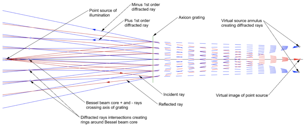
Fig. 4 Creation of a Bessel beam by a point source in reflection from an Axicon grating
Light rays (red) from a point source at the left of Fig. 4 reflect from the Axicon grating. The reflected rays appear to emanate from a virtual point source at the right of the figure. On either side of the reflected rays are plus and minus 1st order diffracted rays (blue) that appear to emanate from a virtual annulus in the plane of the virtual point source. The radius of the annulus is the distance z from point source to grating times the tangent of the diffraction angle α. Diffracted rays from equal and opposite sides of the axis of the grating interfere on the axis of the grating to form the core of the Bessel beam while rays from opposite sides of the axis but different heights at the grating interfere to create the rings around the core.
By looking at the rays impinging on the center of the grating it is clear that there will be ray crossings starting immediately to the left of the grating to form the beginning of a Bessel beam in reflection. As the ray heights increase on the grating the diffracted ray crossings proceed to the left until they reach a height of 4 mm, for our example, where the crossing extends to infinity. Beyond that the diffracted rays start to diverge and create virtual crossings to the right of the grating that mimic the real crossings to the left of the grating.
For the reflected Bessel beam the usual method of creating and observing it would be to use an autostigmatic microscope (ASM) with the point source in the microscope illuminates the Axicon grating and observes the reflected Bessel beam. In this case the reflected Bessel beam length never exceeds the distance from the focus of the ASM to the grating and this distance will be limited by the diameter of the grating. The maximum distance the ASM can be from the grating is limited by the zonal radius of the grating. Once z = Rmax*tan(α) = 393.38 mm, for our example, the virtual annulus is at infinity with a radius of Rmax. As z increases from there the virtual annulus moves to the left of the grating and the diffracted rays diverge so they never enter the ASM objective. The other 1st order rays are always diverging. This means when using an ASM with an Axicon grating in reflection the maximum length of the Bessel beam will be Rmax*tan(α). Since Bessel beams are self-healing12 a point inside the limit just stated will create a Bessel beam to the left of the source provided the source does not obscure too much of the beam.
Another practical aspect of moving the ASM too far from the grating is the objective will have a reasonable NA, typically about 0.3 for a 10x objective. As you move farther from the grating the intensity of the illumination is decreasing as z^2 which is not bad in and of itself, but as the source illumination is increased scattered and ambient sources of light increase the background illumination around the core. The point here is to use the reflected Bessel beam to align the ASM to the grating and then align a point source on the other side of the grating to the ASM to create a longer length useful Bessel beam13. Because the point source creating the transmitted Bessel bean can be placed close to the grating the illumination is intense and the beam as mentioned earlier can go to infinity in theory.
3.2 Properties of Bessel beams created in transmission
Fig. 5 shows what happens when a point source illuminates the grating in transmission. Assume the source is still at 125 mm from the grating but the diffraction angle is 5° to spread the rays for clarity. The Figure shows a point source illuminating the grating with the 0 order rays (red) passing through the grating. On either side of each transmitted ray are plus and minus 1st order diffracted rays (blue) that appear to emanate from an annulus of radius z*tan(α) surrounding the point source. As with the reflected ray case, the diffracted rays on either side of the grating axis and the same height at the grating cross the axis to create the core of the Bessel beam. Rays from differing heights at the grating form the rings around the core.
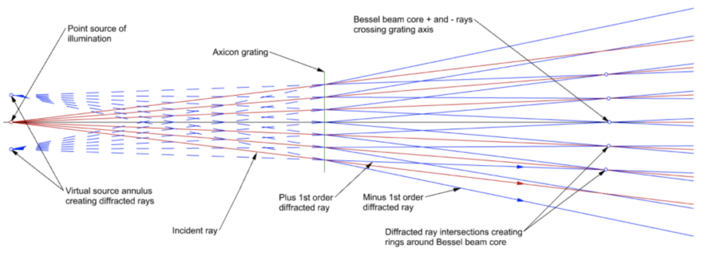
Fig. 5 Bessel beam formation in transmission using a point source of illumination
As long as the point source is closer to the grating than Rmax/tan(α) the Bessel beam propagates from the grating to infinity. This means the Bessel beam created in transmission can be used with greater flexibility than the reflected beam but there does not appear to be a good method of assuring the axis of the Bessel beam is strictly perpendicular to the grating other than aligning the transmitted beam to an ASM that has been previously aligned using the reflection mode. If not aligned in this manner the Bessel beam can be several degrees off perpendicular without affecting the quality of the beam14. In some applications the alignment with the grating makes no difference, for example, when using the beam to determine straightness. However, if the beam is used for alignment it is usually necessary for the beam to be perpendicular to the grating.
3.3 Other practical considerations concerning using Bessel beams
3.3.1 Axicon grating light efficiency
Axicon gratings are not very efficient light wise. At any particular observation point along the Bessel beam you are only seeing the light that make it through an annulus the width of the annulus. For example, the ring at 4 mm radius where the diffracted rays are normal to the grating has an area of 0.2516 mm2 and rings inside this are progressively smaller. This is why the intensity shown in Fig. 2a is low close to the grating. For this reason a SM fiber coupled light source with a variable intensity of several mW is a practical size source. The source does not have to be monochromatic, or even close to monochromatic, to create a Bessel beam. White light will work if you can get enough into a fiber to get useful light in the diffracted beam.
3.3.2 Use of Bessel beams with quad-cells
Keeping with the ring size topic, using a Bessel beam with a quad-cell does not work. The energy spread around the central core is close to uniform because every ring has nearly the same energy as the rings on either side of any particular ring15. The reason it is easy to center on the central core with a digital camera is that the energy density is about 8x greater than in the first ring. When the camera shutter speed is set to give a threshold of about half the peak intensity of the core, the only pixels above the threshold are pixels in the core and centroiding is a simple as finding the center of gravity of the pixels above threshold.
3.3.3 Ease of initial alignment with Bessel beams
On a related topic, because there is energy spread out laterally way beyond the core it is easy to know which way to adjust a mirror or lens to bring the core into the field of view of the microscope objective used to view the Bessel beam. As the intensity of the light source or the shutter speed is decreased, the rings around the central are visible even though the central core is many mm outside the typical field of view of about 1 mm for a 10x objective and modest size format digital camera.
The best way to think about this advantage is to think about aligning an autocollimator to a plane mirror a couple meters away. It is a 2 person job in a darkened room using a flashlight shining in the eyepiece. Once reflected light is back in the objective the job is done, but getting the light in the aperture of the autocollimator is a real trick. With the Bessel beam the rings are a flag waving to tell you which way to tilt the mirror to get light in the aperture even though you are grossly misaligned to begin with.
3.3.4 Aligning point source to the grating axis
The point source illuminating the grating must be on the axis of the grating within limits that are, in practice, fairly loose otherwise the core of the Bessel beam brakes up into a checkerboard pattern of dots. The details of how far off axis are given in this paper by Bin and Zhu16. A method of perfectly aligning the point sources to the grating in either reflection or transmission was previously given13.
In addition, the central core also breaks up if the Bessel beam goes through or is reflected from an optic that introduces sufficient aberration. For example, if a lens is sufficiently tilted relative to the Bessel beam the astigmatism introduced will break the core into a pattern of dots. There is still information in the pattern but it is much harder to interpret than the central core. Again, this topic is beyond the scope but some insight may be gained from Bin and Zhu16. In practice it takes a wavelength or 2 of aberration before there is an effect on the core.
3.3.5 Commercial availability of Axicon gratings
Finally, for those who want to experiment with Axicon gratings they are available commercially for reasonable prices17. If the use of these gratings grows the price is bound to come down.
4. METHOD OF USING A BESSEL BEAM TO FIND TILT AND DECENTER SIMULTANEOUSLY
As a final topic on practical uses of Axicon gratings we describe a method for determining the centering and tilt of a lens without moving anything but the lens itself in 4 degrees of freedom. The principle behind the method is that if we know the location of two points in space we know the origin and slope of the line between the points. What is needed is a device that will sample a Bessel beam simultaneously at two points along the beam. One way of sampling the Bessel beam at two axially displaced locations is to use an optical trombone where one light path goes straight through (blue) while the other (dashed red) is diverted through the trombone to increase its optical path length as shown in Fig. 6. The light arriving in the focal plane of the observing instrument, usually a microscope, comes from two axial locations along the Bessel beam separated by twice the distance of the fold mirrors to the beamsplitters. Before inserting the trombone beam sampling device, the viewing microscope crosshairs are centered on the Bessel beam coming from the Axicon grating. Then the sampler is inserted in the beam. The sampler, depending on the type of beamsplitters used, will shift the beam more or less from the crosshairs if it is not well aligned in angle. Once the sampler is aligned the beam passes through the sampler undeviated as in Fig. 6.
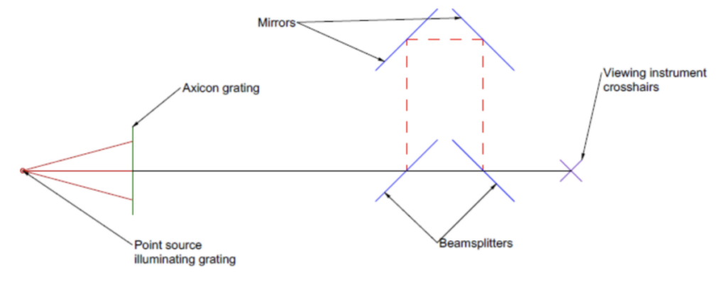
Fig. 6 Axial beam sampler aligned with a Bessel beam and microscope
Adding a tilted and decentered lens element between the grating and the sampler will displace the beam at the microscope focal plane but by different amounts depending on whether the beam has travelled the long or short path as shown in Fig. 7.
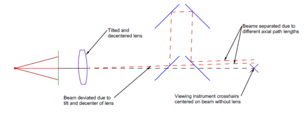
Fig. 7 A tilted and decentered lens inserted between the Axicon grating and the axial beam sampler producing different displacements of the two beams at the focal plane observing microscope
In order to align the lens in both tilt and decentered to the viewing instrument, both central cores of the Bessel beams must lie on the microscope crosshairs. If the observing instrument has a resolution of <1 μm (typical of a Point Source Microscope18 with a 10x objective) and the distance between axial observing locations is 100 mm the lens can be centered to <1 μm and aligned parallel to the axis of the beam to <2 seconds of arc without having to move any part of the observing instrument. The advantages of aligning lenses without having any part of the alignment apparatus move other than the adjustments to the lens itself are obvious for improving productivity.
5. CONCLUSION
We have explained how Bessel beams are created using Axicon gratings and have shown how to calculate the useful range of the beam in reflection. There is no practical limit to the range in transmission. In addition, we have discussed several practical considerations for the use of Bessel beams for alignment in conjunction with observing instruments that use digital cameras. In particular, the ease of alignment if the setup is initially badly misaligned so no bright light is in the sensor field of view. It was pointed out that Axicon gratings are commercially available and that the quality of the Bessel beam produced is a higher quality than those produced by conical axicons although the gratings are only about half as efficient in light use.
Finally we showed how to precision align a lens element in tilt and decenter by using an optical trombone to sample the Bessel beam at two axially separated locations. The technique improves productivity because there are no moving parts in the alignment setup and adjustments to tilt and decenter can be dialed in with adjustment screws.
REFERENCES
[1] Durnin, J., “Exact solutions for nondiffracting beams. I. The scalar theory”, JOSA-A, 4, 651-4 (1987).
[2] McLeod, J. H., “The Axicon: A New Type of Optical Element”, JOSA, 44, 592-7 (1954).
[3] (Personal opinion from meeting McLeod in 1967 at Eastman Kodak Company.)
[4] McLeod, J. H., “Axicons and Their Uses”, JOSA, 50, 166-9, (1960).
[5] Turunen, J., Vasara, A. and Friberg, A., “Holographic generation of diffraction-free beams”, Appl. Opts., 27, 3959 (1988).
[6] Vasara, A., Turunen, J. and Friberg, A., “Realization of general nondiffracting beams with computer generated holograms”, JOSA A, 6, 1748 (1989).
[7] Fortin, M., Piche, M. and Borra, E., “Optics test with Bessel beam interferometry”, Opts. Express, 12 5887 (2004).
[8] Gale, D. “Generacion y aplicacion de haces Bessel en trabajos de alineacion”, Rev. Cub. Fisica, 27, 28 (2010).
[9] Jaroszewicz, Z., Burnall, A. and Friburg, A., “Axicon-the Most Important Optical Element”, Optics and Photonics News, April 2005, p. 34.
[10] J. Ye, M. Takac, C.N. Berglund, G. Owen, R.F. Pease, “An exact algorithm for self-calibration of two-dimensional metrology stages”, Prec. Eng., 20, 16, (1997).
[11] Dong, M and Pu, J., “On-axis irradiance distribution of axicons illuminated by a spherical wave”, Optics & Laser Tech., 39, 1258 (2007).
[12] Bouchal, Z., Wagner, J. and Chlup, M., “Self-reconstruction of a distorted nondiffracting beam”, Optics Communications, 151, 207 (1998).
[13] Parks, R., “Alignment using axicon plane gratings”, Proc. SPIE, 10747, 1074703, (2018).
[14] McGloin, D. and Dholakia, K., ‘Bessel Beams: Diffraction in a new light”, Contemporary Physics, 46, 15-28, (2005).
[15] Durnin, J., Miceli, J. and Eberly, J., “Comparison of Bessel and Gaussian beams”, Opt. Lett. 13, 79 (1998).
[16] Bin, J. and Zhu, L., “Diffraction property of an axicon in oblique illumination,” Appl. Opt. 37, 2563-2568 (1998).
[17] https://optiper.com/en/products/buy/axicon-grating
[18] https://optiper.com/en/products/point-source-microscope