1. INTRODUCTION
The premise of this paper is that the only remaining way to improve optical system performance is with better alignment techniques. We feel optical design is a mature field and that little can be done to improve the design of optical systems by improvements to lens design software. The software may become easier or more convenient to use but the optical designs produced are near optimum given the design constraints specifying the system.
The same holds for the manufacture of optical elements. Between computer controlled manufacturing methods and interferometric testing of the manufactured elements and the many improvements in optical glass quality, not many avenues are open to improved quality of the optical components themselves. The only area left for improvement in performance of precision, or high quality, optical systems is the assembly and alignment of the glass elements and mirrors into mechanical cells, and lens benches, for more complex system geometries.
Based on this premise we will first define our concept of what precision optical alignment means and why traditional methods of alignment have not kept up with the improvements in lens design and the manufacture of high quality optical elements. We contrast traditional methods with more modern methods of optical alignment that make use of optical datums rather than mechanical datums and show the advantages of the optical methods.
Next, we show some advances in the optical methods of alignment including newer optical alignment tools and tooling including gratings that define axes in 5 degrees of freedom and how these make alignment easier. Finally, we look at the implications of these newer methods on how the opto-mechanics of cell and lens bench design are impacted so that tolerances can be loosened while achieving improved optical system performance. While this applies largely to precision optics manufacture, there are aspects of this approach that are applicable to production assembly as well.
2. MEANING OF OPTICAL ALIGNMENT
One might ask why is it even necessary to describe the meaning of alignment until you look in books and papers on optical design and manufacture for the words “alignment” or “centering” in their indices. The words are almost non- existent. This is why I think it is important to write about alignment because few people think about alignment until a kit of optical and mechanical components are set on a table in assembly area along with an assembly drawing. By then it is far too late in the process to make alignment any easier or more precise. Tolerances are assigned to the glass and metal parts in the design phase with the thought that if the parts are assembled per print, a system can be built that will perform as expected, but little thought is given to the process of putting the parts together to the tolerances given.
First, alignment is a paraxial concept based on the radii of curvature of surfaces, and the distances and the index of refraction between surfaces. The angles made a by misalignment are assumed small and the angles of rays through surfaces relative to normals of the surfaces are small enough that the small angle approximation sin α = α holds. This means that even if we want to align a large diameter surface we only have to look at a small region of the surface because we assume the surface is continuous with no abrupt changes.
The next concept is the difference between optical datums and mechanical datums to define alignment. The simplest of all optical surfaces is a spherical surface where we include plano surfaces as spheres with infinite radii, the same as do lens design programs. Optically, spherical surfaces are completely defined by 4 degrees of freedom; the location of the center of curvature and the radius of curvature as is obvious from the defining geometrical equation r^2 = x^2 + y^2 + z^2. However, when that infinitely thin spherical surface becomes physical by giving it some thickness it now has an edge that gives it a mechanical axis, but that axis has nothing to do with how the surface behaves optically.
The simplest way of showing this difference in optical and mechanical behavior is that there are two ways of moving the center of curvature to a particular location in space, either by displacement, or by tilting about the surface as shown in Fig. 1. If light is coming from infinity, or from near the center of curvature, the edge of the spherical surface will not affect how or where the surface focuses the light. At most, the edge will affect uniformity of illumination of the surface.
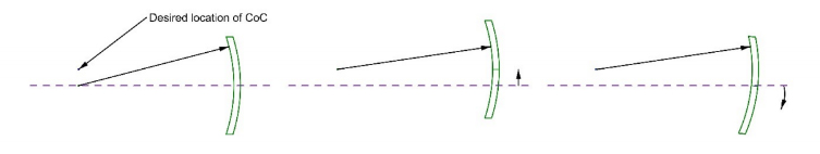
Fig. 1. Moving the center of curvature of a spherical surface by either displacement or tilt.
On the other hand, it pays to point out for future reference that if the location of the spherical surface is defined by a circular seat, it is not possible to move the center of curvature by sliding the surface in the seat. Sliding will move the physical edge of the (infinitely thin) surface but the center of curvature remains fixed in space because the intersection of a sphere cut by a plane is a circle.

Fig 2. Sliding a spherical surface sitting on a circular seat moves its edge but not its center of curvature.
Finally, while a spherical surface does not have an optical axis, a lens with two spherical surfaces or an aspherical surface does have an optical axis. In the case of the lens, the optical axis is the line joining the two centers of curvature, period. The optical axis has nothing to do with the mechanical axis defined by the periphery of the lens. For an aspheric surface, the optical axis is defined the line between the vertex center of curvature and the sagittal center of curvature at the edge of the mirror aperture as in Fig. 3. For a parabola the length of that line is the same as the sag of the parabola, a short distance relative to the diameter unless it is a very fast parabola.
With these concepts in mind, the definition of alignment is to assemble the optical system so the centers of curvature and the optical axes of the components are precisely located as shown in the optical design model on the computer screen of the lens designer. This is simple to say but the actual task to accomplish this precise positioning of optical datums given a pile of discrete glass and metal components set out on an assembly workbench is difficult.
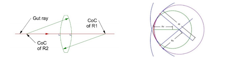
Fig. 3. Optical axis of a lens is line between centers of curvature, axis of asphere is line between the vertex center of curvature and the sagittal center of curvature at the edge of the mirror aperture.
3. TRADITIONAL APPROACHES TO OPTICAL ALIGNMENT
The traditional approach to optical assembly uses mechanical methods for several reasons. A mechanical designer did the mechanical drawings describing both the optical and mechanical components of the assembly. Assuming an incoming inspection was done on the components, mechanical rather than optical inspection was done because it is difficult to impossible to inspect individual lenses for optical quality outside an optical shop and even there it is difficult to do a functional transmission test. The people doing assembly tend to have greater familiarity with mechanical tools like micrometers, indicators and rotary tables than with optical tools like microscopes and alignment telescopes.
The traditional approach to centering lenses in a barrel or cell is to edge the lens to tight tolerances so the optical and mechanical axes are coincident when assembled. The cell is machined to tight tolerances to keep the seat centered and the bore just large enough so the edged lens will just fit. In this case there is no active centering, but reliance on tight tolerances to hold tilt and decenter of the lens to a minimum. However, there must always be a little gap between lens and bore or the lens would not fit in the bore. The tolerance stack up here limits the precision of centering and is costly because of the tight tolerances on both the glass and metal parts.
Another traditional method for perfect alignment, at least in theory, is using a precision rotary table and mechanical indicator. First, the seat is centered using the rotary table to establish a reference axis in space and an indicator to ensure the seat is concentric to the rotary table axis. As mentioned above, the seat will determine the location of the center of curvature of the spherical surface supported by the seat. Then the lens is placed on the seat, and the lens surface directly on the seat is slid on the seat until an indicator placed at the edge of the upper lens surface shows a constant reading. This shows there is a constant thickness of glass between the seat and the upper surface of the lens indicating coincidence of the optical axis of the lens and the rotary table axis, or that there is no wedge between the front and rear lens surfaces. Then the lens is constrained in the cell or barrel.
The positive aspects of the traditional method of centering is that it works, and has worked for many years. Another advantage is that since the elements are actively centered, the tolerances on edging the elements can be looser and the diameters of the bores looser. The seats must be precisely centered as there is no way of perfectly compensating for seat decenter by tilting the lens in the seat. In addition, the equipment used is familiar to most of the people doing the assembly.
Some disadvantages of the method are that it is a contact method and there is the possibility of the indicator tip scratching the lens. The lens being centered is often down inside a cell or barrel and it is sometimes difficult to get the indicator tip positioned on the edge of the lens, particularly with the indicator probe tip at an angle to get maximum sensitivity from the indicator. Further, precision rotary tables are expensive and require periodic maintenance for best performance.
Perhaps the most important shortcoming is that the datum of prime interest, the centers of curvature, are not accessed directly. Rather the position of the center of curvature is surmised from the touch indicator probe rather than measuring the location of the center of curvature directly as can be done optically. Unless the lens radii are very short, monitoring the lens edge is much less sensitive to alignment than viewing the motion of the center of curvature as the cell rotates.
4. NON-CONTACT METHODS OF CENTERING
Most non-contact methods of centering still require a precision rotary table but use an optical sensor to locate the center of curvature or its back focus of the element in question. Some systems also use a collimated beam of light coming up through the rotary table so the optical sensor above the lens can sense a transmitted focus. The sensors in these non-contact systems are autostigmatic microscopes1,2 or their functional equivalent of an autocollimator with a focusing objective3,4.
As centering proceeds, the focused spot viewed by the sensor precesses in synchronism with the rotary table, the magnitude of the precession getting smaller the better the centration. The focused spot stands still when the lens is perfectly centered on the rotary table axis. Among the advantages of this system of alignment is that the vertical column to which the sensor is mounted need not be perfectly aligned parallel to the rotary table axis nor does the column have to be perfectly straight. The indication of “perfect” alignment or centering is that the focused spot remains stationary as the table rotates even though the spot may not appear centered in the sensor’s field of view5.
The reference axis in space is the axis created by the rotary motion of the table and the axis extends without limit above and below the table. The focused spot from the lens conjugate is stationary only when the center of curvature, or back focus, lies on the axis created by the table rotation.
5. CENTERING WITHOUT A ROTARY TABLE
Recently we showed that Axicon gratings also create a reference axis in space without using a rotary table6 This allows non-contact centering while reducing the cost of the centering equipment and simplifying the centering itself. The grating method makes possible the viewing of 2 conjugates of a lens simultaneously, and thus the optical axis of a lens in one measurement. This way tilt and center are adjusted without any movement of the sensor or rotation of the lens being centered. There is immediate hand/eye feedback to the adjustments so the actual centering operation is simple and rapid.
While the method of using an Axicon grating was described previously7, it is worthwhile illustrating again with a simple example of centering a doublet for cementing. Consider the steps in the Fig. 4 to set up the instrument for cementing.
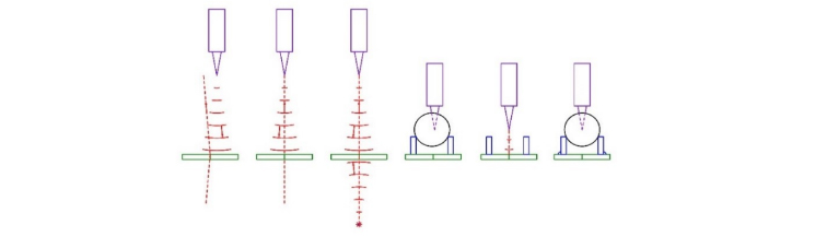
Fig. 4. Steps to align the chuck, or seat, for cementing a doublet
The first picture shows an autostigmatic microscope (ASM) projecting a spherical wavefront from the focus of its objective toward the Axicon grating (green). When the spherical wavefront strikes the grating, diffraction produces two axial beams, one transmitted and one reflected (dotted red lines). The transmitted beam lies on the line joining the objective focus and the center of the Axicon grating pattern. The reflected beam is a mirror image of the transmitted beam.
As the ASM moves to the left in the next picture, the reflected beam appears as a spot on the ASM sensor and moves toward the centered crosshair in the ASM. When the focus of the ASM is on the axis of the grating pattern, the spot lies centered on the ASM crosshairs. With the ASM centered on the Axicon grating, a point source of light behind the grating (red dot) is adjusted laterally until the beam produced by the source is also centered on the crosshairs in the ASM. At this point both the ASM objective focus and the point source behind the grating lie on a line through the center of the Axicon grating pattern and normal to the grating pattern. Assuming a distance of 200 mm from the grating and an ASM sensitivity of 0.2 μm to centering the spot, the ASM and point source are aligned to the grating to 1 arc second.
In the fourth picture, we align the seat for cementing the meniscus half of the doublet to the grating using a spherical ball, for short radii, or the actual meniscus lens for longer radii. Note that the seat must be parallel to the grating as well as centered. The ASM is lowered on the vertical stage until its focus is at the center of the ball. Moving the ASM vertically will usually decenter the ASM from the center of the grating. This is why the ball is temporarily removed from the seat so the ASM can be re-aligned to the grating at this height. The ball is replaced after the ASM centering and the seat is centered so the reflected spot from the ball center is centered on the ASM crosshair with sub-micron precision. Now the seat, or chuck, is fixed in place relative to the grating and is not centered again. This completes the setup for cementing doublets.
Another approach to this setup step is to build the Axicon grating into the chuck so that it is pre-aligned to the grating in centering and tilt. There is no need for further alignment of the two unless there is damage to the lens seat that would disturb the alignment.
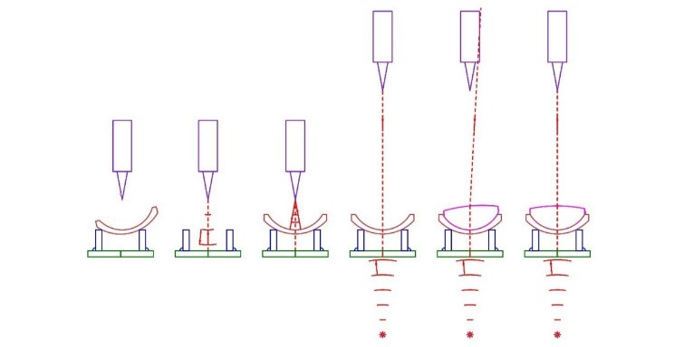
Fig. 5. Steps of aligning the two halves of the doublet for cementing
Fig. 5 first shows the ASM is adjusted vertically to be at the height of the center of curvature of the concave side of the meniscus. Moving the stage vertically will usually decenter the ASM slightly with respect to the grating. In the next picture, the ASM is centered on the grating after removing the lens to remove any misalignment.
Once the ASM is centered, the lens is replaced and slid on its convex surface on the seat until the center of curvature of the concave side lies on the axis of the grating as seen with the ASM. Since the center of curvature of the convex side is already on the axis of the grating because the seat is centered, the optical axis of the meniscus is coincident with the axis of the grating. The meniscus is fixed to the seat so it will not move during the cementing of the positive element. A convenient method of doing this is to use vacuum.
The ASM is moved up above the meniscus to a convenient height where it is out of the way of the cementing operation. The particular height is unimportant because the projected beam from below the grating is not affected by the power of the meniscus as will be shown below. Once the ASM is at a convenient height, the point source behind the grating is illuminated and used to center the ASM laterally. This is a precise centration of the ASM since the meniscus was well centered in both tilt and decenter. The transmitted beam from below the lens is incident on both meniscus lens surfaces at normal incidence so the beam is undeviated.
After placing a drop of cement on the concave surface, the positive element set on the meniscus. Since this element is not centered initially, the transmitted beam will be deviated until the element is centered. Once centered, after the cement is worked to the edge of the lens, the beam will be undeviated as shown in the last picture. The doublet is ready for curing of the cement.
6. INDEPENDENCE OF THE AXICON GRATING WITH LENS POWER
To demonstrate that the beam created by the grating is unaffected in its ability to center a lens independent of the power of the lens a couple of examples are shown in Fig.6.
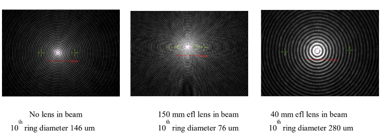
Fig. 6. The spot produced by the transmitted beam through the Axicon grating and lenses of different powers as seen on the video screen of the Point Source Microscope (PSM), a commercial ASM
In the left hand picture of Fig. 6 there was no lens in the beam. In the middle picture, a 150 mm efl lens was inserted and centered. The centroiding algorithm still works just as well as in the left hand picture but the ring spacing is changed. Similarly, for the right hand picture where a 40 mm efl lens was inserted. The scale bar in red shows the same magnification for all 3 pictures and the green crosses were used to estimate the diameters of the 10th rings.
We point out that the reason the centroiding algorithm works in the Point Source Microscope (PSM)1 independent of the ring diameters is that the intensity of the brightest pixels is kept just under saturation when the Auto Gain function is used. Each ring of the spot pattern, including the central spot, has the same energy, but the intensity of the central spot is about 12 times that of the first ring surrounding it8. The centroid is calculated only using pixels within half the intensity of the brightest pixels and thus none of the light in even the first ring is included in the centroid calculation.
Before moving on to the design of hardware making use of these tools, we emphasize the power of these methods, particularly the use of the Axicon grating. The axis created by the grating defines 5 degrees of freedom, 3 translational and 2 angular. In one way, consider the grating a plane mirror with a defined axis strictly perpendicular to the grating surface that is easily located laterally to < 1 μm at almost any distance from the grating.
A further advantage of the Axicon grating is the ease with which the spot is aligned even when grossly misaligned to start with. Because the rings produced by the grating extend beyond the diameter of the grating, the curvature of the grating lines show which way the grating or ASM moves to achieve alignment. This is contrasted with using an autocollimator where most of your time is spent finding the return reflection. With the grating, unless you are vastly misaligned there is always a visible return reflection and that reflection indicates the way to move to achieve alignment of the spot.
No lens in beam 150 mm efl lens in beam 40 mm efl lens in beam 10th ring diameter 146 um 10th ring diameter 76 um 10th ring diameter 280 um
7. DESIGN OF LENS MOUNTING HARDWARE
As pointed out earlier, a spherical surface sitting on a circular seat will always have its center of curvature centered on the circular seat. This means that any lens with a second spherical surface can always be aligned so that the optical axis of the lens is coincident with the axis of the seat by sliding the lens in the seat, or at least until the edge of the lens interferes with the cell bore. The proviso here is that for multiple elements, the seats for the lenses must be concentric and that axis defined by the concentric seats must be aligned to either the axis of a rotary table or the axis of an Axicon grating before the property of tilting lenses is of any use.
This situation calls to mind an illustration in Yoder’s book about opto-mechanical alignment shown below9. Here the primary datum is everyone’s wish, the cell and optical elements are all centered on this datum that is obviously the axis of both the elements and the cell. The problem is finding this axis using practical hardware, and is it an optical or a mechanical datum? It seems to me that much more practical datums would be the face of the cell as the A datum where it would sit on a surface plate or rotary table, and the B datum a bore in the cell. This gives a meaningful way of calling out other feature tolerances relative to easily accessible datum features rather than something that only is useful to the optical designer.
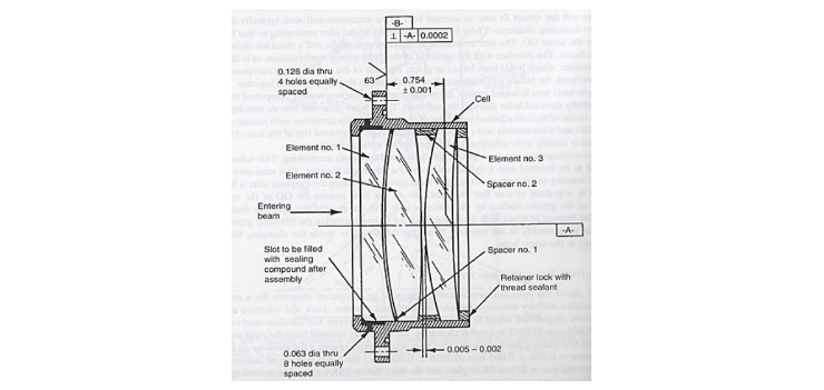
Fig. 7. Drawing of a lens assembly with an ambiguous primary datum (P. Yoder, Opto-Mechanical Systems Design)
Perhaps a fairer way of looking at Fig. 7 is to assume this is the assembled lens and the B datum should be perpendicular to A for mounting of the whole lens. However, the Figure is a great example of what to avoid when making mechanical drawings, datums that have little relevance to actual methods of inspection and assembly.
The text accompanying the Figure talks about the tight tolerances on the lenses and cell to achieve precision centering10. The tight tolerances mean expensive components and a difficult and risky job of assembly. Inserting close fitting elements into a tight bore call for a very steady hand. The least mis-alignment as the element is inserted in the cell will cause the element to jam against the bore. The element must never be forced, but gently backed out and inserted again. There is a high likelihood of chipping the element in this process.
Counter to this example, I would suggest the method used in microscope objective assemblies and that used for most lithographic lenses, cells, or bond rings, for each element going into an assembly as shown in Fig. 8 of this microscope objective. Notice every pair of elements is mounted in its own cell and, where possible, against a spherical surface. The design is complex enough that all details are not apparent in the picture but the concept is clear. By mounting each element is its own cell it is possible to align the optical axis of the element perpendicular to the face of the cell. Then as the individual cells are assembled, the only alignment is decenter and element to element spacing. This approach decouples tilt from decenter so the alignments are independent of each other.

Fig. 8. Cross section of a high power microscope objective
Another advantage with simpler systems than microscope objectives is you are not working down a bore but the lens vertices are largely co-planar with the faces of the individual cells. This makes it easy to measure lens vertex to cell face spacing and ultimately to correct element spacing during the centering step of assembly without having to worry about lens tilt. The method is largely self checking in that as cells are stacked up, the upper most cell face should be parallel to the bottom of the stack, and the thickness of the stack is easily measured via the cells rather than having to indicate off the lens vertices.
The idea of using bond rings, or individual cells, is not new. Yoder has several examples of this method of assembly and alignment11. However, there is little emphasis on the advantages of this approach to assembly and alignment, some of which have already been mentioned. An even greater advantage than assembling lenses in a barrel comes with 2 or 3 dimensional optical layouts.
When lenses are assembled in a barrel, it is usually the case that gravity is working for you. In multi-dimensional cases, the system often cannot be orientated so that gravity aids the assembly. Decenter is not a big problem because it is easy to fixture a situation where 2 plane surfaces have to slide over each other to achieve alignment. Conversely, it is quite difficult to fixture an element that must rotate when it is not being held down by gravity. If an element can be mounted free of tilt in a plane cell with gravity aiding the alignment, and then centered against another plane surface where gravity is not helping, this is so much easier than fighting gravity where it is a tilt adjustment, or much worse fighting with tilt and decenter simultaneously.
We use an example where a rectangular lens was edged out of a symmetric meniscus far enough off axis that the mechanical axis of the symmetric lens missed the rectangular aperture. The lens was then aligned to an “L” shaped mount in 5 degrees of freedom using a sophisticated fixture that allowed fine adjustment in the 5 degrees of freedom. We used two PSMs and an auxiliary lens to simultaneously locate both centers of curvature of the lens and guide the lens into position to be cemented. The alignment was quite easy but did required a fancy fixture with 7 precision stages. Fig. 9 shows the alignment setup.
Note the two tooling balls in Fig. 9 that locate the centers of curvature of the 2 sides of the rectangular lens (sitting in front of the upper laptop). Also, note the auxiliary lens next to the laptop that converges light onto the convex side of the lens. When the lens is not in the fixture light from the auxiliary lens focuses at the center of the tooling ball nearest the lens. The tooling balls are removed during the alignment of the lens so both lens surfaces are seen simultaneously.
If instead the lens had been bonded in a cell that removed the tilt and then slid over a plane mounting surface machined into the lens bench at the correct angle relative to the other components the need for the complex fixture and dual ASMs would not be needed. Fig. 10 shows the same optical features as Fig. 9 with the 2 centers of curvature defining the optical axis of the lens and the rectangular lens hidden inside the lens mount (green). The lens and mount sit on a photomask substrate that has a set of Fresnel zone patterns defining the locations of precision steel balls that then kinematically define the locations of the lens and mounting frame12,13. The layout of the photomask patterns is shown as a top view in Fig. 11.
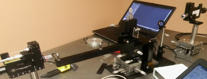
Fig. 9 Setup for aligning a rectangular meniscus lens to a mount via a precision fixture
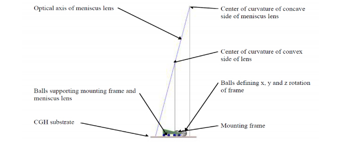
Fig. 10. Side view of a simple fixture to align the rectangular lens shown in Fig. 9
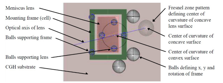
Fig. 11 Top view of the fixture used for alignment of the rectangular lens to is mount
Before describing the layout in Fig. 11 we should explain the use of the Fresnel zone rather than Axicon patterns on this photomask substrate. In the same manner as the equally spaced concentric rings of the Axicon grating, a pattern of Fresnel zone rings of varying spacings and widths are written on the substrate. By choosing the correct parameters, the Fresnel patterns will behave optically identically to concave spherical mirrors of a specific radius of curvature14.
By making the radii match the radii of steel balls, an ASM is first aligned to the center of curvature of the Fresnel pattern that is one radius above the substrate, and then a ball of that same radius is cemented to the substrate after being aligned to the ASM. Using this, technique the balls are aligned spatially to tolerances of about 1 μm in x and y. The Fresnel zone patterns typically have an overall spatial registration to the design location of 30-40 nm on a 150 mm square photomask substrate16.
In Fig. 11 the 3 balls under the pink rectangular lens define the location of the center of curvature of the convex surface of the lens in the same manner as a circular seat in the case of a symmetric lens15. The 3 balls under the green lens mount define the plane of the mount while the 3 balls at the edges of the mount define its x, y and z rotation. These 3 balls are unnecessary in theory because we will use these degrees of freedom to align the lens to the lens bench, but the mount must be held in place during cementing of the lens to the mount so these balls prove useful in a capacity other than alignment. In other situations, it is clear there is the possibility to completely define the location of the mount using the grating pattern and balls.
Prior to cementing the lens in the mount, an ASM is centered so the focus of its objective is at the center of curvature of the Fresnel zone pattern that defines the location of the center of curvature of the concave side of the lens. The lens is slid on the 3 balls until the reflected spot is centered on the ASM crosshairs, an indication that the optical axis of the lens is located correctly relative to the lens mount. Once cemented in its mount, the lens can be aligned to a plane surface in the lens bench by decenter alone by viewing a light beam produced by an Axicon grating. The mounted lens is slid on a plane surface of the lens bench machined at the correct angle until the Axicon beam shows no deviation with the lens in place.
Contrast of the 2 methods of alignment is stark. One photomask with a custom set of Fresnel zone patterns replaces one ASM, 9 or 10 precision stages and a sizable bit of real estate on an optical table. Further, in the actual cementing operation the method using the photomask is much easier ergonomically.
8. CONCLUSIONS
We have claimed that alignment is the only area where precision optical system performance can be improved and have attempted to show that traditional mechanical methods of improving alignment are difficult. Improvements to the precision of alignment and the ease of assembly are relatively easy to make if one thinks about alignment in the design phase of the system and applies optical rather than mechanical methods of alignment.
9. ACKNOWLEDGEMENT
The author acknowledges the help of Dr. Chenyu Zhao of Arizona Optical Metrology for providing prototype Axicon and Fresnel zone gratings.
10. REFERENCES
[1] https://optiper.com/products/point-source-microscope
[2] https://opt-e.com/wp-content/uploads/2016/02/Opt-E-W2-2016-02-13-1.pdf
[3] https://trioptics-usa.com/products/opticentric
[4] https://www.optoalignment.com/las-bt-vis
[5] Parks, R. E., “Practical alignment using an autostigmatic microscope”, Proc. SPIE 8491, 84910H (2012).
[6] Parks, R. E., “Alignment using Axicon plane gratings”, Proc. SPIE 10747, 1074703 (2018).
[7] Parks, R. E., “New approach to optical assembly and cementing”, Proc. SPIE 10747, 107470C (2018).
[8] Liu, X. and Xue, C., “Intensity distribution of diffractive axicon with the optical angular spectrum theory”, Optik 163, 91-8 (2018).
[9] Yoder, P., [Opto-Mechanical Systems Design, 3rd ed.], CRC Press, Boca Raton, FL, p. 238 (2006).
[10] Ibid.
[11] Yoder, op. cit., pp. 285-97.
[12] Coyle, L., Dubin, M. and Burge, J., “Low uncertainty alignment procedure using computer generated holograms”, Proc. SPIE 8131, 81310B (2011).
[13] Parks, R. E., “Optical alignment using a CGH and an autostigmatic microscope”, Proc. SPIE 10377, 1037703 (2017).
[14] Coyle, op. cit.
[15] Parks, R. E., “Computer generated holograms as fixtures for testing optical elements”, Optical Design and Fabrication 2017 (Freeform, IODC, OFT), OSA Technical Digest (online) (Optical Society of America, 2017), paper JTh4B.4.
[16] Ekberg, P. and von Sydow, A., “Past and future challenges from a display mask writer perspective”, Proc. SPIE, 8441, 84410N (2012).