From the beginning we have said that centering a lens meant aligning the optical axis of the lens to a reference axis. Up to this point we have assumed the axis was the mechanical axis of a rotary table. Because there are disadvantages to using a rotary table, I was curious to see if there was another way to create a reference axis. The path to a new axis came from the subject we have been discussing, the cementing of doublet lenses. The idea also came from my interest in computer generated holograms (CGH) for use as calibration artifacts for coordinate measuring machines and CNC machine tools. [1]
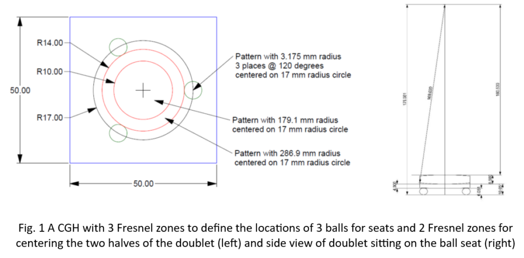
As we have discussed, the seat of the convex side of the meniscus half of a doublet determines the location of the center of curvature of that side. The center of curvature of the concave side is the second point defining the lens axis. It is easy to design a CGH of Fresnel zone patterns to serve as datums for cementing 3 balls to the CGH centered on a Fresnel zone of the correct radius to match the location of the center of curvature of the concave side looking through the lens. [2] A combination of the seat and center of curvature make precision centering the meniscus easy when a centering sensor is centered on the center of curvature.
A second Fresnel zone of a different radius is designed to focus at the same height when the positive element is placed on the meniscus. This means that the meniscus is first aligned and fixed in place and then the positive element aligned to the meniscus without ever having to move the alignment sensor. If the sensor does not have to move it cannot introduce errors due to its movement. Top and side views of such a CGH and doublet alignment scheme are shown in Fig. 1.
As you can read about the successful experiment in the reference there is no need for the details here. While the CGH did exactly what was intended it meant that a different CGH would be required for every different doublet design. Also, this design using balls to serve as a seat made it difficult to secure the aligned meniscus so it would not move when adding and aligning the positive element.
This success coupled with the use of a zone plate CGH to measure the straightness of travel of mechanical ways on machine tools [1] lead to the idea of using the “beam” of light created by the zone plate as a universal method of centering doublets and other alignment tasks. The concept of using a zone plate for alignment purposes is not new. In the 1950’s the Dutch optical scientist A. C. S. van Heel discussed the problem of aligning multiple points to a line because it is difficult to see all the points at once [3]. He goes on to suggest using diffraction by a slit for alignment in one axis before generalizing the idea to use a zone plate of evenly spaced concentric circles. He says that under good observing conditions alignment to 1 µradian is possible. [4]
In 1954, John McLeod of Eastman Kodak, also interested in alignment, invented the Axicon [5] in part to improve the light efficiency of alignment instruments. He said that by illuminating the axicon with a pinhole source of light it “will project a continuous straight line of image out to infinity.” In Fig. 1 of his paper, he shows a diagram that is very close to that in the paper by Durnin [6] that shows how an illuminated annular mask creates a beam of light coined by him as a Bessel beam.
Technology has made great progress since the days of van Heel and McLeod. The zone plates van Heel used were made by light grinding of rings in a polished glass plate to create rings that would transmit and block the light. The rings were typically 1 mm in width. Later the rings may have been made photographically but I could not find a reference. McLeod’s axicons were not the easiest optics to make either, and it wasn’t long after Durnin’s paper that Turunen, et. al. [7] showed that it was easy by then to make zone plates as computer generated holograms (CGH) with narrow line spacings.
It turns out in hindsight that both van Heel and McLeod were producing and using Bessel beams for alignment purposes. It took about 30 years for theorists to review their experimental results and add a theoretical explanation to the phenomenon described by the earlier empirical observations.
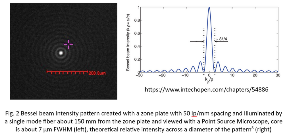
This is a good place to describe a simple Bessel beam as it turns out there are many variations. The simplest beam has an intensity distribution perpendicular to the direction of propagation proportional to the square of the 0 order Bessel function as in Fig. 2 (right), and the intensity distribution captured on a digital camera in Fig. 2 (left). The first ring of the pattern has 16% the intensity of the central peak, and the peak and each ring has the same radiant energy. This means it is easy to precisely centroid on the peak with a digital camera to a small fractional of a pixel if the peak covers a diameter of 3–4 pixels. Because the irradiance of the pattern is nearly constant, a quadcell is useless for centroiding.
Most discussions of Bessel beams assume the illumination of the axicon, or zone plate is collimated. With collimated illumination the beam is a finite length. A point source of light is also a suitable source and produces a beam of close to infinite extent. The source does not have to be coherent or monochromatic. White light works fine. Each of these changes gives a slightly different formal name to the kind of Bessel beam and the ones I use by illuminating a grating with the end of a single mode fiber and laser diode source should probably be called Bessel-Gauss beams.
Now that I have described what a simple Bessel beam is and how they are produced we should get back to the way they propagate through optical systems and why they are useful for alignment. After some initial experiments over 3 years ago using the Bessel beams to measure the straightness of ways on machine tools and realizing errors in transverse motion of a fraction of a µm were easily observed, I began watching what happened when I moved a lens through the beam. I found that when my ASM was focused inside a lens at what appeared to be the principle plane, the transmitted beam did not move as the lens was moved perpendicular to the beam. It did move one way above the plane and the other on the opposite side of the apparent principle plane. This is paraxial rather than real ray behavior.
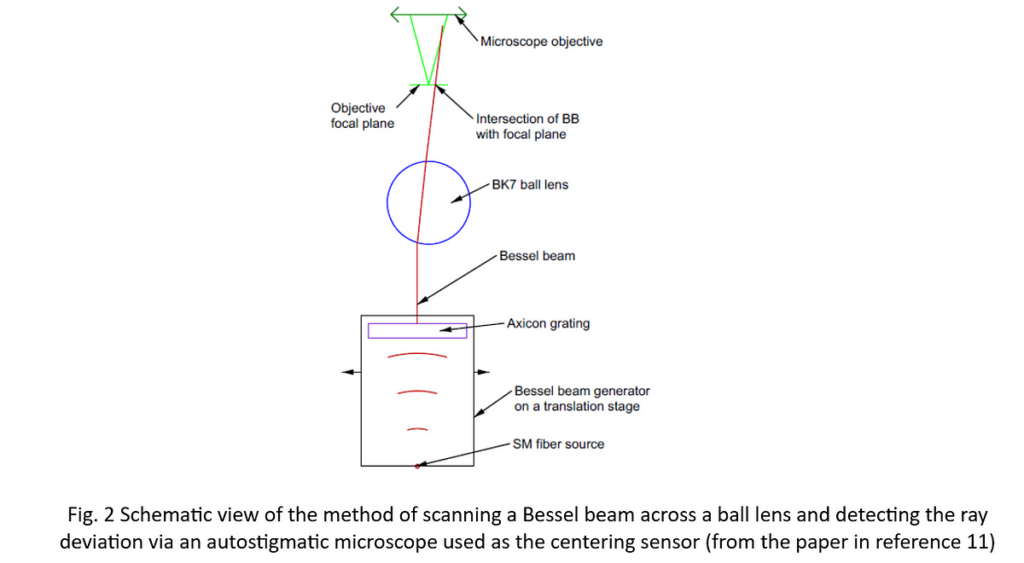
In the meantime, I found the paper “Propagation of generalized Bessel-Gauss beams through ABCD optical systems” [9] that implies the behavior I was seeing was paraxial. This prompted me to do an experiment with a ball lens and create the Bessel beam with a 50 lp/mm axicon grating from AOM. [10] A ball was used since it is always free of tilt and all I had to control was the decenter, or ray height, of the Bessel beam incident on the 8 mm diameter, BK7 ball.
In the experiment, [11] the ball lens and microscope were stationary, and the Bessel beam was translated across the ball close to the ball center to keep the experiment paraxial. For this BK7 ball with an index of 1.515 the efl is 5.8834 mm. If the ball is decentered 1 µm the ray will exit the ball at an angle of h/efl = .001/5.8834 = .00017 radians. The intersection of the entering and exiting rays was at the mid-plane of the ball, its principle plane. The experiment confirmed the paraxial behavior of the Bessel beam.
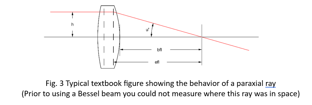
This paraxial behavior has profound consequences relative to alignment and to measuring lens properties in general. The transverse position of the beam can be measured anywhere along the beam including inside the ball, lens or system of lenses. Or far from the lens so a small angular deviation causes a large transverse displacement. Just like the classical textbook picture, Fig. 3, from geometrical optics, if the incident ray is parallel to the lens optical axis it changes direction at the second principle plane to cross the optical axis at the focal point of the lens. (The region right around the focal point is the only place the Bessel beam cannot be viewed because it turns into an annulus.)
Because the Bessel beam behaves as a single paraxial ray it is easy to calculate the ray deflection angle due to decenter as simply the decenter over the efl. This immediately gives an idea whether a particular height above the lens will be sufficient to give the required sensitivity. If the lens sits in a centered seat, then tilt of the lens changes the ray angle by (R1/efl) times the lens tilt.
For our example meniscus a decenter of 10 µm changes the ray angle by .01/-110.66 = -9.04 µradians and a lens tilt of 1 mradian changes the ray angle by (264.97*.001)/-110.66 = 2.394 mradian. Not surprisingly lens elements with short focal lengths are more sensitive to misalignment than ones with longer focal lengths, or less power.
We have covered many topics in this Chapter, so it is time for a quick review.
· The expense and tediousness of using a rotary table for lens centering led me to look for an alternative method
· An initial use of a Fresnel zone CGH was successful centering but not practical
· Experience with zone plates made with CGH techniques for mechanical alignment led me to try them for optical alignment
· The Bessel beams made by the zone plates appeared to propagate through optical elements and systems as though they were paraxial rays
· Published works and further experiments convinced me the propagation was paraxial
· This meant the Bessel beam position could be measured anywhere along the beam
· In turn this means it is easy to measure the beam angle exiting a lens to find centering errors independent of where center of curvature are located
In the next Chapter we will look at more consequences of the paraxial behavior of Bessel beams and their application to centering and alignment.
References
[1] Parks, R., Ziegert, J. and Groover, J., Computer Generated Holograms as 3-Dimensional Calibration Artifacts, Proc. ASPE, 117–20 (2017)
[2] Parks, R. Optical alignment using a CGH and an autostigmatic microscope, Proc. SPIE, 10377, 1037708 (2017) also https://www.opticalperspectives.com/category/published-papers/page/3/
[3] van Heel, A. C. S., High Precision Measurements with Simple Equipment, JOSA 40 (12) 809 (1950)
[4] van Heel, A. C. S., ed., Advanced Optical Techniques, Wiley & Sons, NY, pp. 451–2 (1967)
[5] McLeod, J., The Axicon: A New Type of Optical Element, JOSA, 44 (8) pp. 592–7 (1954)
[6] Durnin, J., Exact solutions for nondiffracting beams. I. The scalar theory, JOSA A 4, (4) 651–4 (1987)
[7] Turunen, J., Vasara, A. and Friberg, A., Holographic generation of diffraction-free beams, Appl. Optics, 27 (19) 3959–62 (1988).
[8] Costanzo, S., https://www.intechopen.com/chapters/54886
[9] Santarsiero, M., Propagation of generalized Bessel-Gauss beams through ABCD optical systems, Optics Communications, 132 (1996) pp. 1–7
[10] Arizona Optical Metrology https://cghnulls.com/
[11] Parks, R. and Kim, D., Physical ray tracing with Bessel beams, Proc. ASPE Spring Topical Meeting 2023 (This paper is available as a sidebar to the Chapters on alignment at https://medium.com/@reparks_11319/introduction-to-a-series-of-articles-on-optical-alignment-4d2bf0282e33 )