For some time, I wanted to simulate the assembly of a Cooke triplet using a Bessel beam as a reference,
and assuming the hardware constrained the alignment of each element to either a tilt or decenter as is
the case for many precision lens assemblies. A new optical design software is now available that makes
this modelling relatively easy whereas I was struggling before. What I discuss here was done in about 2
hours using KostaCloud, https://kostacloud.com, a software that has many features that make this sort
of modelling easy.
Fig. 1 shows the order of assembly in a typical cell where the central element must be inserted first
because of its small diameter. Because the surfaces are concave, these type elements generally have a
plane annulus ground on both sides that sit against the seat and a retaining ring. I have assumed that
this element has a 1 mradian tilt error in the ground surface so the optical axis of the lens is tilted about
3 minutes of arc, a maximum typical centering tolerance for catalog optics.
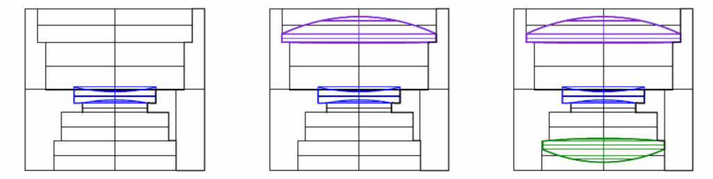
Fig. 1 Assembly steps for a Cooke triplet in a cell where the central element is inserted first
The assembly layout is shown in Fig. 2 and Table 1 is the lens design.
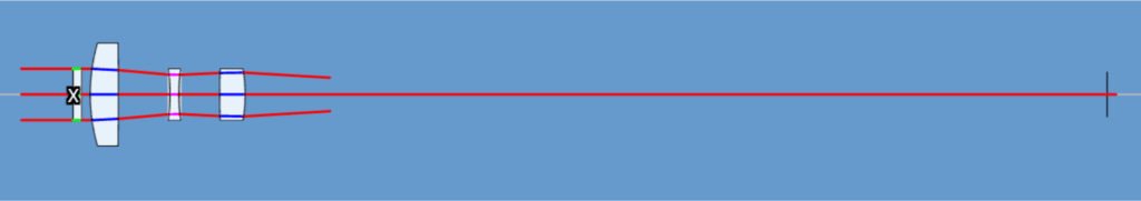
Fig 2 Assembly layout with a Bessel beam detector 100 mm from the lens
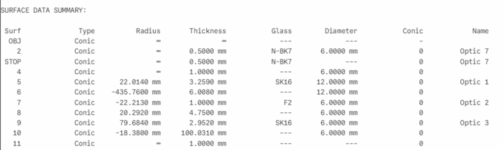
Table 1 Cooke triplet design including a dummy stop element and a detector plane
The plano first element in the design looks odd, but this is to get around a design feature where the stop
is the reference element in the design, and if the element with the stop moves so does the reference
frame and this is what we want to avoid during alignment. Putting the stop on the first surface of the
dummy element assures a fixed global coordinate system origin (the X) without impacting the design in
any other way. On the right of Fig. 2 is a detector plane (black line) that is the focus of a PSM prealigned
to a Bessel beam coming from the left.
The negative element is inserted in the cell with its 1 mradian tilt but perfectly centered. The tilt
introduces a deviation in the gut ray so that the ray is decentered 1.6 µm when it gets to the detector as
shown in Table 2, the ray trace of the system with just the central element.
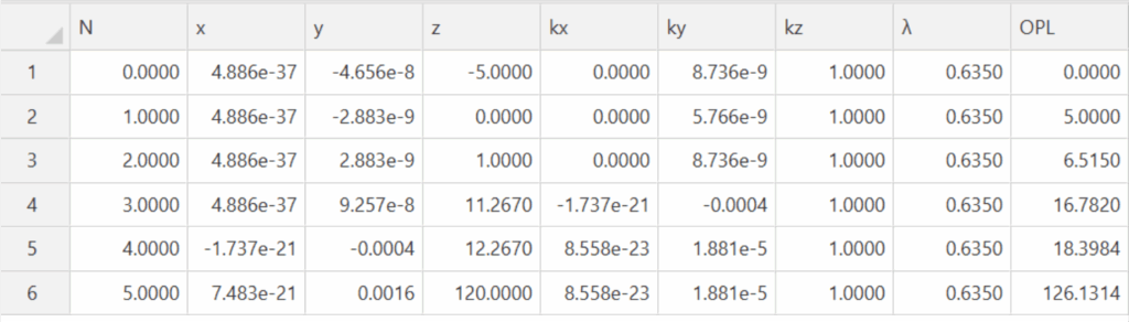
Table 2 Ray trace through the dummy surface and central element (lines 4-5)
As seen in Table 2, the first and last elements of the triplet are missing. A feature of the KostaCloud
software is that you can drag elements out of the beam and then snap them back in, element by
element for each step of the assembly. This makes it easy for modelling an assembly as you can see what
happens as each element is added as in Fig. 3.
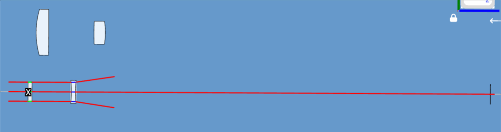
Fig. 3 Alignment configuration used to create the ray trace in Table 2
If the central element is decentered +254 nm the gut ray is centered on the detector to better than 36
nm as seen in line 6 of Table 3. The residual ray angle is now about 4 µradians instead of 19 µradians.
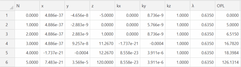
Table 3 Ray trace after decentering the central element 254 nm
When the first element is inserted perfectly centered to the design it will have no effect on the gut ray
because the ray is perfectly centered on the element as seen in Fig. 4 and Table 4. In practice, when the
first element is inserted, it would have to be centered by sliding it over its seat or effectively rotating it
about the center of curvature of the 435 mm radius surface. The PSM can detect decenters of <1 µm and
a rotation of 0.5 µradian would cause this much decenter so the PSM sensitivity to alignment is great.
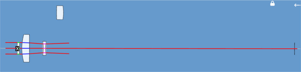
Fig. 4 Assembly after the insertion of the first element
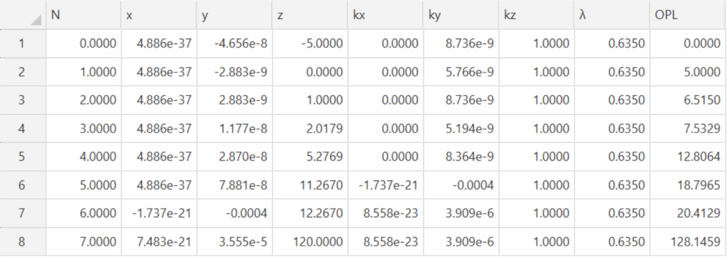
Table 4 Ray trace after the insertion of the first element (lines 4-5)
Finally, we add the last element. In actual assembly the cell would be inverted to assemble the element.
In the design program there is no need to invert the design since the ray trace through the system will
behave similarly either way the ray goes. Fig. 5 shows the complete assembly and Table 5 the ray trace.
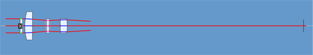
Fig. 5 The assembly after inserting the last element
We assume the last element goes in perfectly centered to the nominal system. However the ray coming
from the central element is slightly tilted and decentered relative to the design axis the last element will
deviate the gut ray as shown in Table 5 by 1.5 µm when it reaches the PSM at an angle of 19 µradians. To
eliminate this decentration at the PSM, the element is rotated about the center of curvature of its first
surface by 4.63 µradians to center the beam on the PSM as shown in Table 6.
The KostaCloud software makes this easy by permitting a shift of the reference point for each element to
either surface or to the center of curvature of either surface by a right click on the element as shown in
Fig. 6. The reference is returned to the initial location once the rotation is accomplished by another right
click.
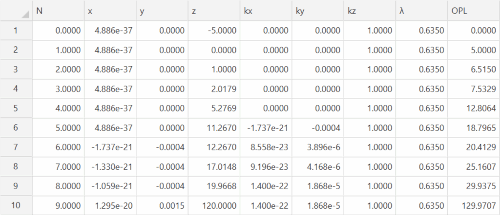
Table 5 Ray trace after inserting the last element (line 8-9)
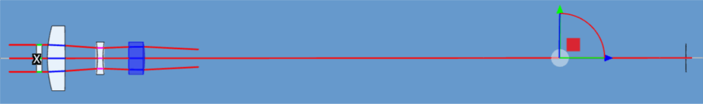
Fig. 6 Last element first surface center of curvature reference position
Once the last element is rotated so the Bessel beam is centered on the PSM we have the rays and angles
shown in Table 6.
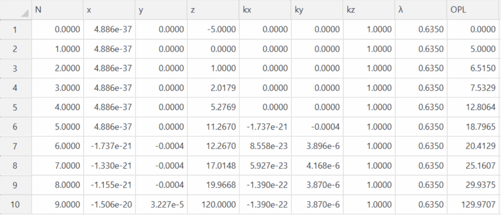
Table 6 Ray trace after rotation of the last element about the center of curvature of its first surface
Not only is the beam centered on the PSM but the gut ray angle leaving the assembly is reduced from 19
µraduans to about 4 µradians. Also, notice the ray never deviates from the design centerline by more
than 0.4 µm nor with an angle great the 400 µradians and that is inside the central element that is tilted
1000 µradians. Otherwise, all the ray angles are single digit µradians.
All this alignment was done without ever moving the PSM from its initial position of 100 mm above the
assembled lens. While the alignment perturbations in this example may be unrealistically small in
practice, they do illustrate the sensitivity of to alignment errors and the simplicity of this method of
alignment where some degrees of alignment freedom are constrained by the hardware design.
Now that we have illustrated the method, could the assembly be done any more precisely if the PSM
were farther from the lens? We will repeat the exercise with the PSM at 500 mm from the lens.
Here is the ray trace after correcting for the tilt of the central element by decentering 307 nm in Table 7.
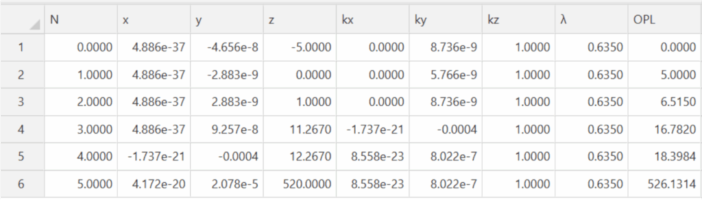
Table 7 Ray trace after inserting the central element with the PSM at 500 mm from the lens
The greater distance gives more sensitivity to the alignment and relative to the first case the angular
error is less, now 0.8 µradians as opposed to 3.9, roughly the same ratio as PSM distance from the lens
change.
As before, when the first element is added there is no change because the first element is perfectly
aligned. Now a 0.1 µradian rotation about the center of curvature will cause a 1 µm decenter of the
PSM, up from 0.5 µm due to the greater path.
A -5.7 µradian tilt about the first surface CoC of the last element reduces the decenter on the detector to
a few nm so there is higher sensitivity to alignment as shown in Table 8. The other significant factor is
that the residual ray angle is now 0.7 µradians as opposed to 3.9 µradians, again an improvement equal
to the increased distance.
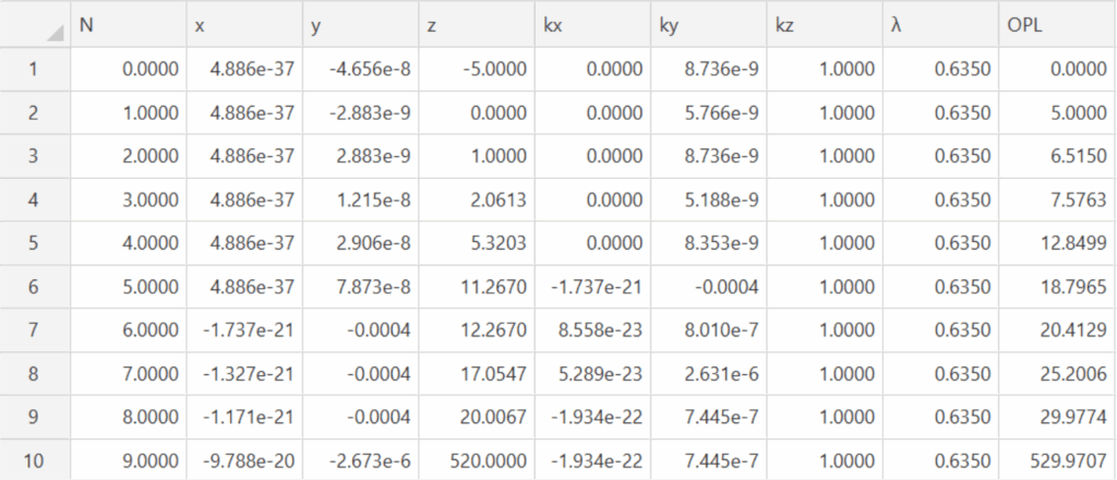
Table 8 Ray trace data after fully aligning the Cooke triplet with the PSM 500 mm from the lens
This brief demonstration shows this method of alignment is not only simple but that the best alignment
is achieved by moving the PSM as far as possible from the lens being assembled. Not only does this give
higher sensitivity to alignment errors but keeps the metrology equipment far from the vicinity of the lens
so it is easier to accomplish the alignment. The method also opens the path to automated alignment of a
whole class of optical products.